A system and method for on-line real-time self-calibration of a clamp ammeter

A clamp ammeter, self-calibration technology, applied in the direction of measuring electrical variables, instruments, measuring devices, etc., can solve the problems that the measurement error accuracy and consistency of the clamp ammeter cannot be guaranteed, the measurement error becomes larger, and the error becomes larger, etc., to achieve The effect of improving convenience, improving accuracy, and saving rotation costs

Active Publication Date: 2022-07-08
ZHUHAI KEHUI ELECTRICAL APPLIANCE CO LTD
View PDF6 Cites 0 Cited by
  • Summary
  • Abstract
  • Description
  • Claims
  • Application Information

AI Technical Summary

Problems solved by technology

The above improvements have optimized the measurement error of the clamp ammeter to a certain extent, but they have not fundamentally solved the problem: only the error at the time of optimization or for a period of time after calibration can be calibrated, but in the long-term use of the field, there are problems affected by the field environment, its own Aging, rusting of the jaws or foreign matter leads to larger measurement errors; on-site operator operations (such as changes in the clamping position between the jaws of the clamp ammeter and the measured line) lead to larger errors or inconsistencies; for Dynamic changes in working conditions during the measurement process (such as relative position changes between the jaws of the clamp ammeter and the measured line) cannot be calibrated, so the measurement error accuracy and consistency of the clamp ammeter cannot be guaranteed

Method used


Image

  • A system and method for on-line real-time self-calibration of a clamp ammeter
  • A system and method for on-line real-time self-calibration of a clamp ammeter
  • A system and method for on-line real-time self-calibration of a clamp ammeter

Examples


Embodiment Construction

[0040] The present invention will be further described in detail below with reference to the accompanying drawings and specific embodiments.

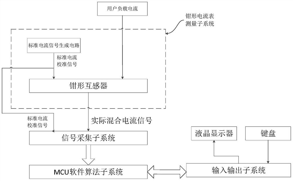
[0041] This embodiment provides an online real-time self-calibration system for a clamp ammeter, such as figure 1 As shown, it includes: a clamp-type ammeter measurement subsystem, a signal acquisition subsystem, an MCU software algorithm subsystem and an input and output subsystem; the clamp-type ammeter measurement subsystem includes a standard current signal generation circuit and a clamp-type transformer. The current signal generation circuit is used to generate the standard current calibration signal and output it to the clamp transformer and the signal acquisition subsystem. The clamp transformer is used to sample the standard current calibration signal and the user load current, and then convert the standard current calibration signal and the user load current. The actual mixed current signal obtained by mixing the signals is out...


PUM


Abstract

The invention discloses an online real-time self-calibration system and method for a clamp-type ammeter. The system includes a clamp-type ammeter measurement subsystem, a signal acquisition subsystem and an MCU software algorithm subsystem; the clamp-type ammeter measurement subsystem includes a clamp-type ammeter measurement subsystem. Transformer, the clamp current meter measurement subsystem is used for generating a standard current calibration signal, sampling a standard current calibration signal and sampling a user load current signal, and then combining the generated standard current calibration signal and the standard current passing through the clamp transformer The actual mixed current signal obtained by mixing the current calibration signal and the user load current signal is respectively output to the acquisition subsystem; the signal acquisition subsystem is used for A / D acquisition of various input current signals, and then the sampled The A / D data is output to the MCU software algorithm subsystem; the MCU software algorithm subsystem is configured to run a self-calibration algorithm on the acquired A / D data to perform real-time self-calibration.

Description

technical field [0001] The invention belongs to the technical field of ammeter self-calibration, and in particular relates to a system and method for on-line real-time self-calibration of a clamp-type ammeter. Background technique [0002] A clamp-type ammeter is an instrument used to measure the current of a running electrical circuit. It can measure the current using the principle of electromagnetic induction without interruption. [0003] Attached to the description of the Chinese utility model CN2125144U figure 1 The basic principle of the clamp-type ammeter is disclosed in: The AC signal of the tested wire is converted into an AC voltage signal through the magnetic induction coil wound on the iron core, and the signal is conditioned and amplified by the current, and then sent to the A / D chip for sampling. The CPU reads the A / D sampling results for calculation and displays the test results. The clamp-type ammeter using this structure has the problem of low accuracy, an...

Claims


Application Information

Patent Timeline
Patent Type & Authority Patents(China)
IPC IPC(8): G01R35/00G01R19/25
CPCG01R35/005G01R19/25
Inventor 朱亚军
Owner ZHUHAI KEHUI ELECTRICAL APPLIANCE CO LTD
Why Eureka
Try Eureka