Reflective liquid crystal display panel

A liquid crystal display panel, reflective technology, applied in the direction of instruments, nonlinear optics, optics, etc., can solve the problems of slow response speed and low contrast of reflective liquid crystal display panels, and achieve auxiliary deflection, improve contrast, and improve response speed Effect

Active Publication Date: 2020-04-17
KUSN INFOVISION OPTOELECTRONICS
View PDF5 Cites 4 Cited by
  • Summary
  • Abstract
  • Description
  • Claims
  • Application Information

AI Technical Summary

Problems solved by technology

[0005] The object of the present invention is to provide a reflective liquid crystal display panel to solve the problems of low contrast and slow response speed of the reflective liquid crystal display panel

Method used


Image

  • Reflective liquid crystal display panel
  • Reflective liquid crystal display panel
  • Reflective liquid crystal display panel

Examples


no. 1 example

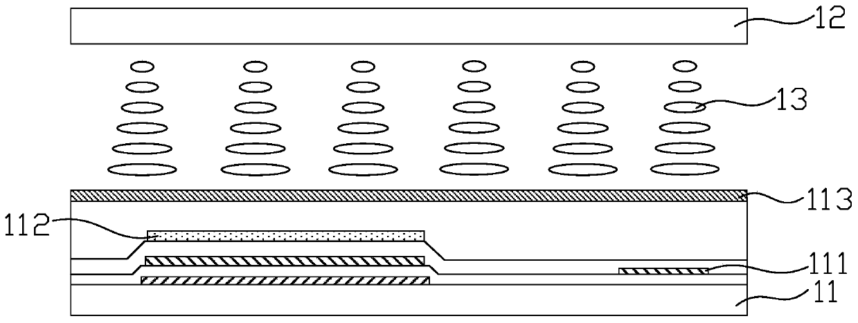
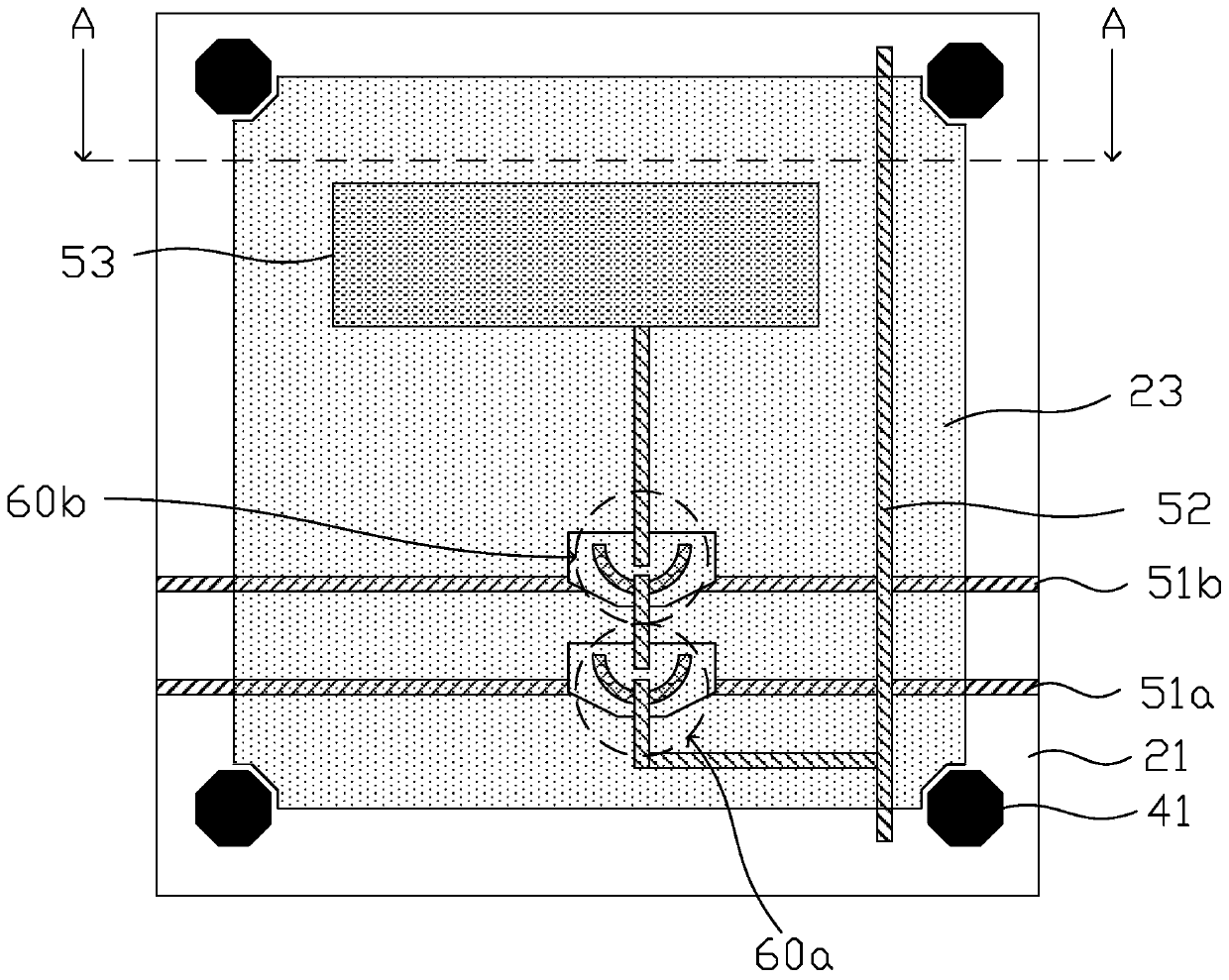
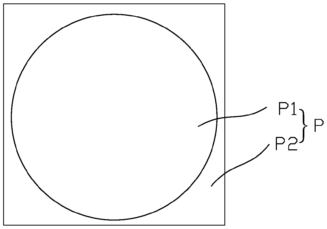
[0029] figure 2 It is a schematic diagram of the pixel structure of the reflective liquid crystal display panel according to the first embodiment of the present invention, image 3 for figure 2 A schematic diagram of partitioning of a single pixel unit P of a reflective liquid crystal display panel shown, Figure 4 for figure 2 The cross-sectional schematic diagram of the reflective liquid crystal display panel shown along the A-A section line in the dark state, please refer to Figure 2 to Figure 4 , the reflective liquid crystal display panel includes a first substrate 20 and a second substrate 30 disposed opposite to each other and a liquid crystal layer 4 between the first substrate 20 and the second substrate 30, and is provided with a plurality of pixel units P arranged in an array , each pixel unit P includes a pre-tilt region P1 and a flat region P2 disposed around the pre-tilt region P1. The first substrate 20 is provided with a common electrode 21 , a pluralit...

no. 2 example

[0040] Figure 9(a) and Figure 9(b) are schematic diagrams of the method for forming the insulating layer in the reflective liquid crystal display panel of the second embodiment of the present invention, referring to Figure 9(a) and Figure 9(b), the second embodiment of the present invention The difference between the reflective liquid crystal display panel provided in the example and the above-mentioned first embodiment is that the insulating layer 24 is formed of photocurable resin, and a part of the photocurable resin is polymerized by ultraviolet light irradiation so that the photocurable resin forms a tapered groove. The photo-curable resin includes a plurality of monomers 240 , and the photo-curable resin is first coated on the basis of forming the pixel electrode 23 , and the monomers 240 are evenly distributed in the photo-curable resin. Then set up a mask 70 (mask) above the light-curable resin, the mask 70 is provided with a light-transmitting area 71 and a non-light-t...


PUM

PropertyMeasurementUnit
thicknessaaaaaaaaaa
thicknessaaaaaaaaaa
thicknessaaaaaaaaaa

Abstract

The invention provides a reflective liquid crystal display panel. The reflective liquid crystal display panel comprises a first substrate, a second substrate and a liquid crystal layer located betweenthe first substrate and the second substrate, the reflective liquid crystal display panel is provided with a plurality of pixel units arranged in an array mode, and each pixel unit comprises a pre-tilt area and a flat area arranged around the pre-tilt area; a common electrode, a plurality of reflective pixel electrodes and an insulating layer covering the pixel electrodes are arranged on the side, facing the liquid crystal layer, of the first substrate, and each pixel electrode is located in the corresponding pixel unit. And the thickness of the insulating layer is gradually reduced from theedge of the pre-inclined region to the center of the pre-inclined region. According to the reflective liquid crystal display panel, dark-state light leakage can be avoided, the contrast ratio can be improved, the conical groove formed by the insulating layer plays a role in assisting deflection of liquid crystal molecules, and the response speed is increased.

Description

technical field [0001] The invention relates to the field of display technology, and more particularly to a reflective liquid crystal display panel. Background technique [0002] With the rapid development of display technology, various technologies emerge in an endless stream, and the applied products are also various. The previous form of relying on drawing paper to display publicity has been gradually replaced by display screens, which are not only diversified, but also energy-saving and environmentally friendly. For example, electronic labels used to replace traditional paper labels are favored by shopping malls, and shopping malls no longer need to worry about frequently posting price tags. [0003] Electronic tags often use reflective liquid crystal display panels, relying on reflected natural light to achieve display. figure 1 It is a structural schematic diagram of a reflective liquid crystal display panel in the prior art, please refer to figure 1 A reflective li...

Claims


Application Information

Patent Timeline
Patent Type & Authority Applications(China)
IPC IPC(8): G02F1/1337
CPCG02F1/133753G02F1/133761G02F1/133776
Inventor 梁文龙
Owner KUSN INFOVISION OPTOELECTRONICS
Why Eureka
Try Eureka