
Lens driving motor, camera and mobile terminal

A lens driving and motor technology, applied in the field of cameras, can solve the problems of poor performance of the lens driving motor, etc.

Pending Publication Date: 2020-04-17
SHANGHAI BILLU ELECTRONICS CO LTD
View PDF0 Cites 5 Cited by
  • Summary
  • Abstract
  • Description
  • Claims
  • Application Information

AI Technical Summary

Problems solved by technology

[0006] The main purpose of the present invention is to provide a lens drive motor, a camera and a mobile terminal to solve the problem of poor usability of the lens drive motor in the prior art

Method used


Image

  • Lens driving motor, camera and mobile terminal
  • Lens driving motor, camera and mobile terminal
  • Lens driving motor, camera and mobile terminal

Examples


Embodiment Construction

[0043] It should be noted that the embodiments in the application and the features in the embodiments can be combined with each other if there is no conflict. Hereinafter, the present invention will be described in detail with reference to the drawings and in conjunction with the embodiments.

[0044] It should be pointed out that, unless otherwise specified, all technical and scientific terms used in this application have the same meanings as commonly understood by those of ordinary skill in the technical field to which this application belongs.

[0045] In the present invention, if there is no explanation to the contrary, the directional words used such as "up, down, top, bottom" are usually directed to the direction shown in the drawings, or refer to the vertical, In terms of vertical or gravitational direction; similarly, for ease of understanding and description, "inner and outer" refers to the inner and outer relative to the contour of each component itself, but the above-men...


PUM


Abstract

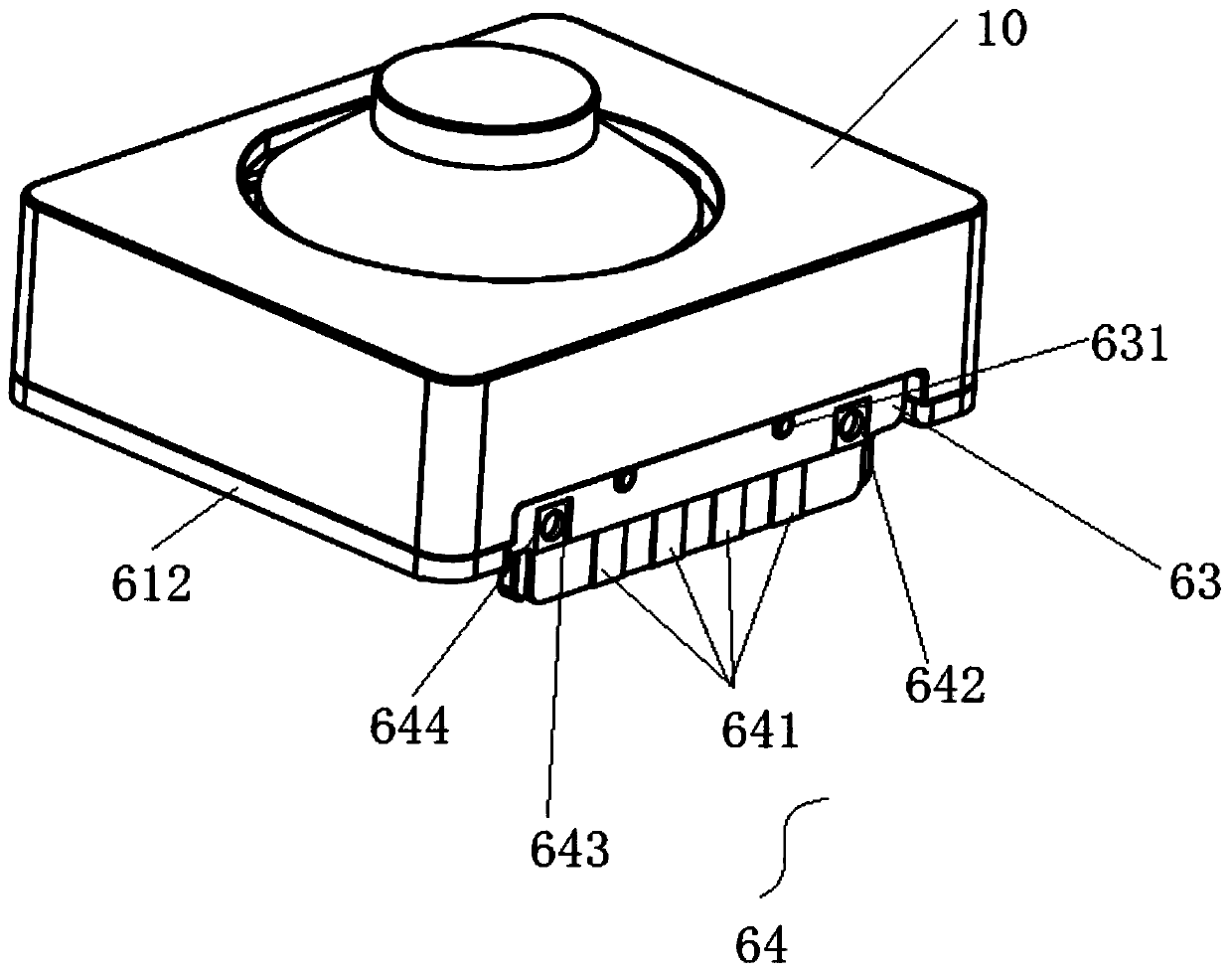
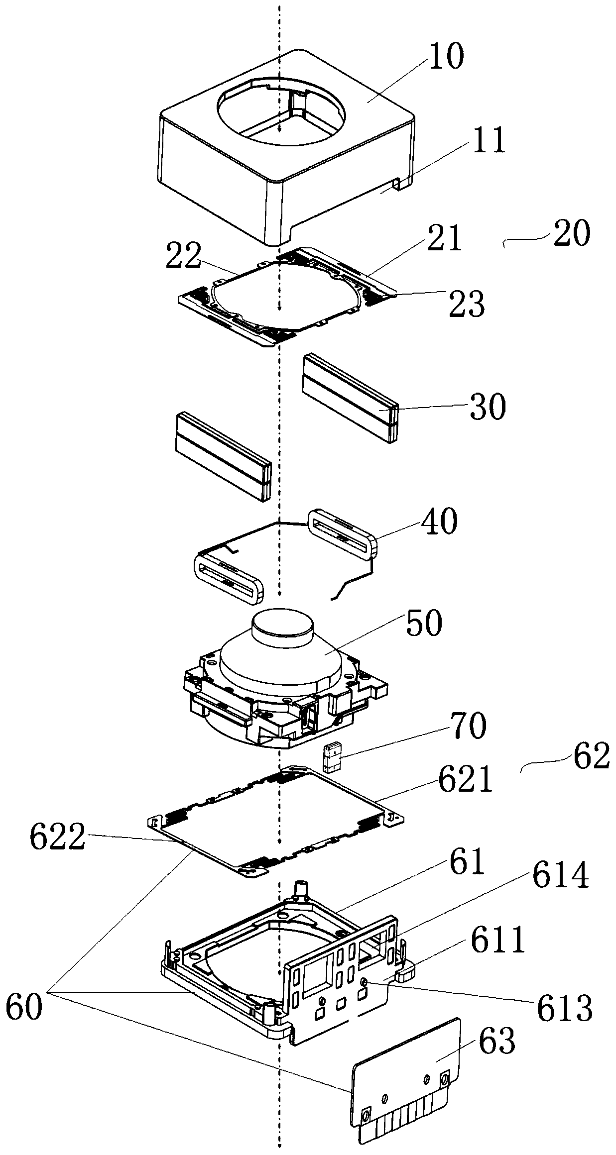
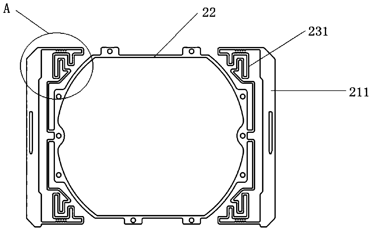
The invention provides a lens driving motor, a camera and a mobile terminal. The lens driving motor comprises a shell, an upper spring, a driving magnet, a driving coil, a lens supporting body and a lower cover assembly. The shell is arranged on the lower cover assembly to form an accommodating space between the shell and the lower cover assembly; the driving magnet, the driving coil and the lenssupporting body are all located in the accommodating space, the driving coil is arranged on the lens supporting body, the driving magnet is arranged corresponding to the driving coil, the upper springis arranged between the shell and the lens supporting body. The upper spring comprises an outer ring structure connected with the shell, an inner ring structure connected with the lens supporting body, and a middle structure through which the outer ring structure and the inner ring structure are connected. A plurality of protruding parts are arranged on the middle structure, and at least two protruding parts extend in the direction close to each other to form an oiling gap. The lens driving motor solves the problem of poor use performance of the lens driving motor in the prior art.

Description

Technical field [0001] The present invention relates to the technical field of cameras, in particular to a lens drive motor, a camera and a mobile terminal. Background technique [0002] The main principle of the lens drive motor of the traditional camera module is to control the stretching position of the VCM spring sheet by changing the DC current of the coil in the motor in a permanent magnetic field and converting the current into mechanical force to drive the lens to move up and down. The function of lens focusing can achieve the purpose of moving the entire lens in a small distance, changing the focal length, and achieving a clear image. [0003] In recent years, the closed loop motor (Close Loop Motor) that has appeared in the market as a new technology has formed a closed loop system with focus position feedback function after the addition of the Hall chip, which has improved the focus speed and focus accuracy to a certain extent. However, as with other types of motors, it...

Claims


Application Information

Patent Timeline
IPC IPC(8): G03B13/34G02B7/04H02K41/035G03B30/00
CPCG03B13/34G02B7/04H02K41/0354
Inventor 龚高峰王建华凌彩盛
Owner SHANGHAI BILLU ELECTRONICS CO LTD
Learn More