Double-layer coil end three-electrostatic-ring structure

A coil end, electrostatic ring technology, applied in the field of transformers, can solve the problems of complex structure, cumbersome winding, affecting the mechanical strength and electric field distribution of the double-layer coil ascending layer, etc., so as to increase the insulation margin and improve the electric field distribution. Effect

Pending Publication Date: 2020-04-17
BAODING TIANWEI BAOBIAN ELECTRICAL
View PDF0 Cites 0 Cited by
  • Summary
  • Abstract
  • Description
  • Claims
  • Application Information

AI Technical Summary

Problems solved by technology

Due to the different winding directions of the inner and outer coils of the double-layer coil of the transformer, the electromagnetic wires of the inner and outer coils have opposite slopes at the ascending layer, and the single-layer oblique electrostatic ring cannot be placed. Different slopes can be placed evenly, the structure is complex, and the winding is cumbersome, which affects the mechanical strength and electric field distribution of the double-layer coil at the ascending layer

Method used


Image

  • Double-layer coil end three-electrostatic-ring structure
  • Double-layer coil end three-electrostatic-ring structure
  • Double-layer coil end three-electrostatic-ring structure

Examples


Embodiment Construction

[0020] The technical solutions of the present invention will be further described in detail below in conjunction with the accompanying drawings and embodiments.

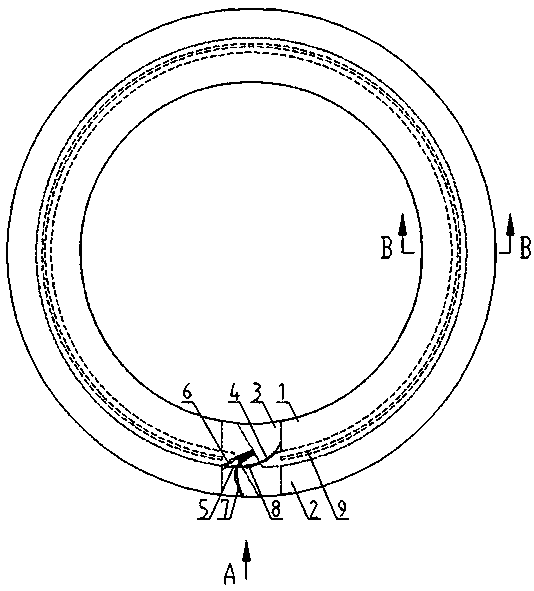
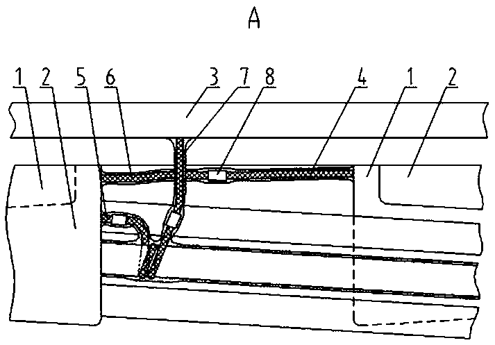
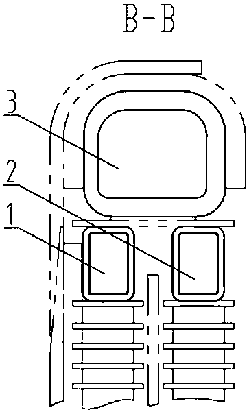
[0021] A structure of three electrostatic rings at the end of a double-layer coil, including an inner oblique electrostatic ring 1, an outer oblique electrostatic ring 2, an end static electrical ring 3, an inner oblique electrostatic ring equipotential lead-out wire 4, and an outer oblique electrostatic ring The lower equipotential lead wire 5, the upper equipotential lead wire 6 of the outer oblique static ring, the equipotential lead wire 7 of the end static electric ring, the crimping joint 8 and the insulating cylinder 9, and the inner oblique electrostatic ring 1 is placed in the inner layer At the ascending level of the coil, the outer inclined electrostatic ring 2 is placed at the ascending position of the outer coil, the inner inclined electrostatic ring 1 is opposite to the outer inclined electrostatic ring ...


PUM


Abstract

The invention relates to a double-layer coil end three-electrostatic-ring structure, and belongs to the technical field of transformers. According to the technical scheme, an inner-layer inclined electrostatic ring (1) is placed at an ascending position of an inner-layer coil, an outer-layer inclined electrostatic ring (2) is placed at an ascending position of an outer-layer coil, the inclinationof the inner-layer inclined electrostatic ring is opposite to that of the outer-layer inclined electrostatic ring, and end part flat electrostatic rings (3) is placed at the end parts of the outer-layer inclined electrostatic ring and the inner-layer inclined electrostatic ring; an inner-layer inclined electrostatic ring equipotential leading-out wire (4) is connected with an outer-layer inclinedelectrostatic ring upper equipotential leading-out wire (6); a coil conductive wire is welded to an equipotential leading-out wire, one end of the equipotential leading-out wire is connected with an outer-layer inclined electrostatic ring lower equipotential leading-out wire (6), and the other end of the equipotential leading-out wire is connected with an equipotential leading-out wire of the endflat electrostatic ring. The electrostatic ring is divided into the inner inclined electrostatic ring, the outer inclined electrostatic ring and the end flat electrostatic ring which are directly placed at the ascending position of the double-layer coil, so that the electric field distribution at the ascending position is effectively improved, and the insulation margin of the transformer and the mechanical strength of the double-layer coil are increased.

Description

technical field [0001] The invention relates to a structure of three static rings at the ends of double-layer coils, which belongs to the technical field of transformers. Background technique [0002] In a power transformer, due to the uneven distribution of the electric field near the ascending layer of the double-layer coil winding, the insulation strength at the end of the winding is reduced, and the discharge phenomenon is prone to occur and damage the transformer. In order to improve the electric field distribution near the end line section of the winding ascending layer and reduce the surface field strength of the electrostatic ring, three electrostatic rings are set at the ascending layer of the winding, the inner layer coil is thinly insulated and oblique electrostatic ring, and the outer layer coil is thinly insulated oblique electrostatic ring , and the thick insulated static electric ring covering the inner and outer coils upwards. Its function is that the inner a...

Claims


Application Information

Patent Timeline
IPC IPC(8): H01F27/32H01F27/34
CPCH01F27/324H01F27/34
Inventor 王二涛刘力强于素梅张计英谢京张永恒张宏斌
Owner BAODING TIANWEI BAOBIAN ELECTRICAL
Why Eureka
Try Eureka