Apparatus for growing ceramic coating by electrolyte injection discharge and method thereof

A ceramic coating and electrolyte technology, applied in the field of ion body electrolytic oxidation process, can solve the problems of restricting technology promotion, decline, waste of resources, work efficiency, etc., so as to increase the cathode area, improve the film formation speed and quality, and optimize the electric field. The effect of distribution

Inactive Publication Date: 2012-06-13
INST OF MECHANICS - CHINESE ACAD OF SCI
View PDF5 Cites 11 Cited by
  • Summary
  • Abstract
  • Description
  • Claims
  • Application Information

AI Technical Summary

Problems solved by technology

[0004] The existence of the above-mentioned problems greatly increases the difficulty of using PEO technology in actual industrial production and limits the promotion of technology, which will cause unnecessary waste of resources and a decline in work efficiency

Method used


Image

  • Apparatus for growing ceramic coating by electrolyte injection discharge and method thereof
  • Apparatus for growing ceramic coating by electrolyte injection discharge and method thereof

Examples


Embodiment 1

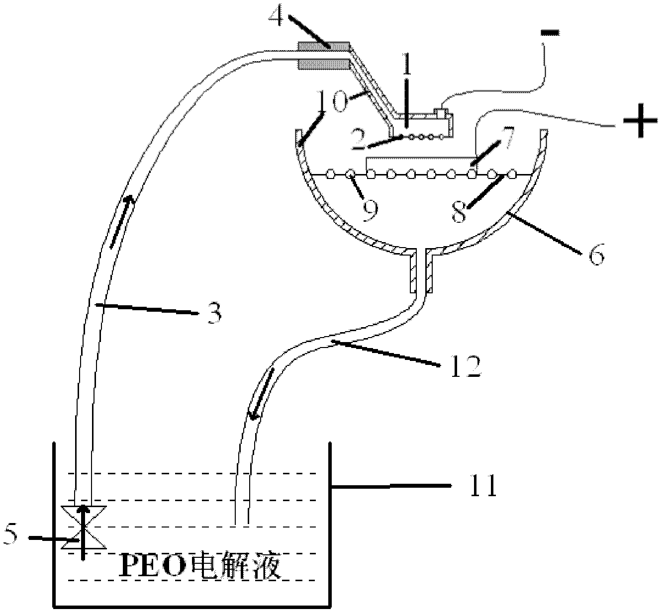
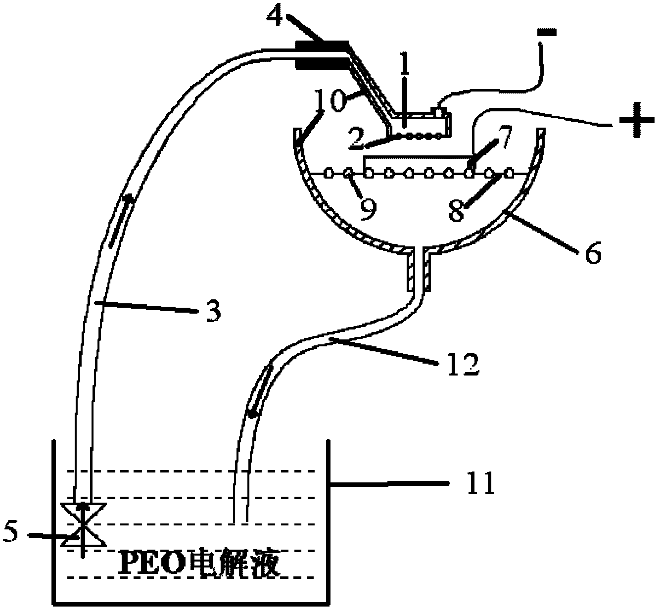
[0038] Such as figure 1 As shown, the cathode system is designed as a hand-held spray head, which is made of stainless steel. In the area of ​​50mm×2000mm on the bottom surface of the head body 1, there are spray holes 2 with a diameter of φ2mm and a distance between the centers of adjacent holes of 3mm. The handle 4 adopts Made of bakelite material. The inner cavity of the head body 1 is connected with a liquid inlet pipe 3 made of plastics, and the liquid inlet pipe 3 is connected with the micro circulation pump 5 in the electrolytic cell 11 . Below the nozzle, a large stainless steel material funnel 6 (i.e. electrolyte collection tank) is placed, on the funnel 6 is provided with a stainless steel flat plate 8 (i.e. a mounting platform) for placing the sample 7 to be processed, on the stainless steel flat plate 8 there are a large number of The through hole 9 is used to discharge the electrolyte, and a liquid outlet pipe 12 made of plastic is arranged below the funnel, and ...

Embodiment 2

[0041]When locally repairing five large defects of 100 mm × 100 mm on the surface of the magnesium alloy workpiece, the nozzle holes 2 are set in the area of ​​50 mm × 100 mm on the bottom surface of the cathode nozzle body 1, and the position to be repaired is first cleaned and removed before PEO treatment. Oil pretreatment, and then place the workpiece as a whole on the stainless steel plate 8 (ie, the mounting table), and expose the first position to be repaired under the nozzle. Using the device and operation method similar to the above-mentioned Example 1, fix the workpiece, hold the cathode nozzle to move at a speed of 5mm / min in the plane area to be treated, and complete the repair of the first damaged position after 20 minutes. Move the second position to be repaired to expose it under the nozzle. The operation process is similar to that of the first position. After 20 minutes, the repair of the second damaged position is completed. Similarly, PEO treatment was perform...


PUM

PropertyMeasurementUnit
thicknessaaaaaaaaaa

Abstract

The invention discloses an apparatus for growing a ceramic coating by electrolyte injection and discharge. The apparatus contains an electrolytic tank used for storing a PEO electrolyte, a nozzle used to spray the electrolyte on a sample to be treated after the electrolyte stored in the electrolytic tank is pumped in through a circulating pump, a workpiece carrying bench which is positioned below the nozzle, used to carry the sample to be treated and provided with through holes for drainage of the injected electrolyte, and an electrolyte collection tank which is used to collect the electrolyte flowed out from the through holes. The electrolyte is directed into the electrolytic tank through a drain pipe. The invention also discloses a method for growing the ceramic coating by electrolyte injection and discharge. The invention brings forward a novel PEO film forming method which is suitable for workpiece local respiring or large-area workpiece surface continuous treatment. Simultaneously, a PEO processing apparatus with a plating mode is designed. Therefore, the technology for workpiece local respiring or large-area workpiece surface continuous treatment is simple and easy to operate, and the film forming efficiency is raised.

Description

technical field [0001] The invention relates to the technical field of plasma electrolytic oxidation technology, in particular to a device and method for growing a ceramic coating by spraying and discharging electrolyte. Background technique [0002] Plasma Electrolytic Oxidation (Plasma Electrolytic Oxidation, PEO) is also known as "micro-arc oxidation" or "spark discharge anode deposition". Electrochemical surface treatment technology that acts on the electrode surface to grow ceramic layers in situ. Through this technology, a ceramic layer with high film base bonding strength and high hardness can be obtained on the surface of aluminum, magnesium, titanium and other alloys, thereby overcoming the shortcomings of soft alloy base, poor corrosion resistance and wear resistance. Compared with other surface treatment technologies, this technology has the advantages of high film forming efficiency, simple process, controllable film performance and environmental protection. ...

Claims


Application Information

Patent Timeline
Patent Type & Authority Applications(China)
IPC IPC(8): C25D11/02
Inventor 夏原李光刘晓静
Owner INST OF MECHANICS - CHINESE ACAD OF SCI
Why Eureka
Try Eureka