
A portable cable binding fixture

A fixed and portable technology, applied in cable laying equipment and other directions, can solve the problems of increased maintenance costs, inconvenient use, and low operation efficiency.

Active Publication Date: 2021-04-16
STATE GRID SHANDONG ELECTRIC POWER COMPANY WEIFANG POWER SUPPLY +1
View PDF7 Cites 0 Cited by
  • Summary
  • Abstract
  • Description
  • Claims
  • Application Information

AI Technical Summary

Problems solved by technology

[0003] In order to solve the problems that today’s cable binding tools are generally bulky and inconvenient to use, while manually binding cables, the work efficiency is low, manpower and material resources are wasted, and the binding force cannot be accurately controlled, which may damage the cables and increase maintenance costs. A portable cable binding fixture

Method used


Image

  • A portable cable binding fixture
  • A portable cable binding fixture
  • A portable cable binding fixture

Examples


Embodiment Construction

[0022] Embodiments of the present invention will be further described below in conjunction with the accompanying drawings.

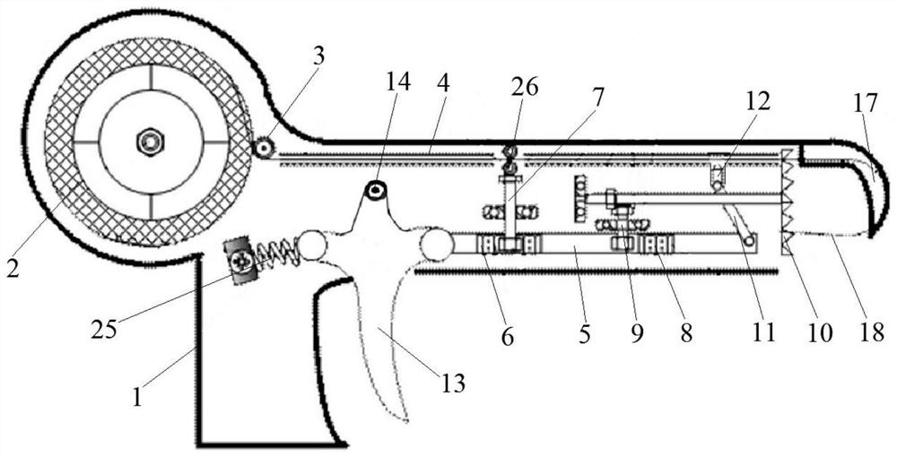
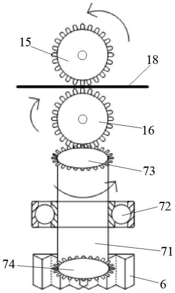
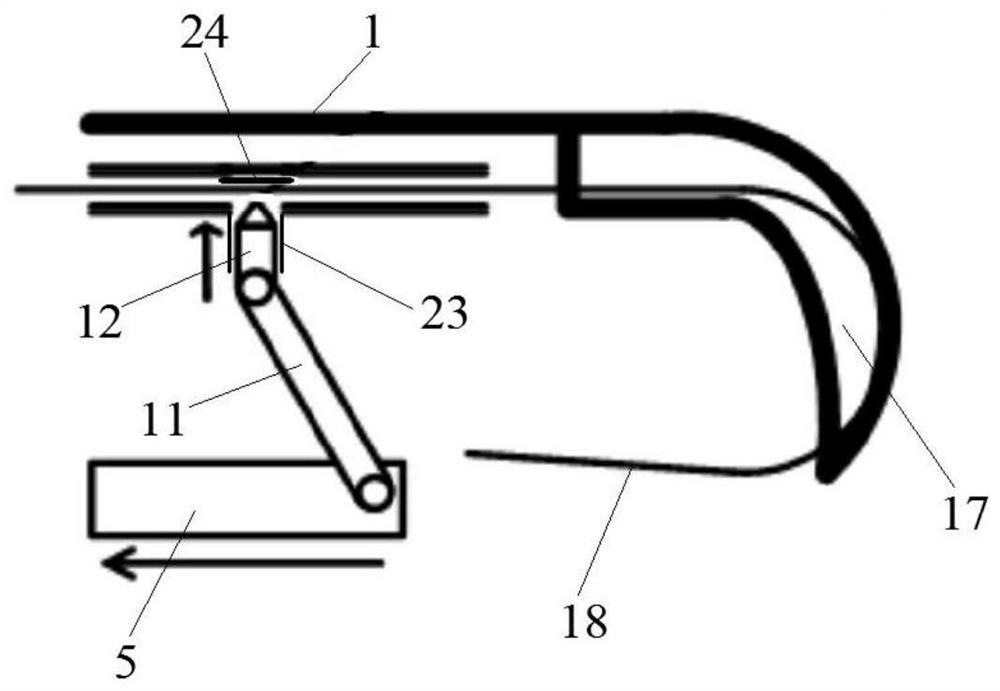
[0023] As shown in the accompanying drawings, a portable cable binding fixture includes a housing 1 in which a wire transmission channel 4, a trigger 13 and a wire tray 2 for winding iron wire 18 are installed, and the iron wire transmission channel 4 and the wire binding disc 2 are provided with a guide wheel 3 of a guide wire 10. The front side of the trigger 13 is connected with a transmission rod 5 that can slide back and forth. The trigger 13 is installed in the housing 1 through a rotating shaft 14. The trigger 13 The rear side is connected with the housing 1 via a spring 25 . The front end of the wire transmission channel 4 is provided with an arc-shaped fixed hook 17, and the inner surface of the fixed hook 17 is provided with a guide groove. The binding disc 10 is provided with a circular array of two rings of hollowed out slots 22 , and the sl...


PUM


Abstract

A portable cable binding fixer, belonging to the technical field of cable laying, comprising a housing, in which an iron wire transmission channel is provided, a forward conveying device is provided in the middle of the iron wire transmission channel, a cutter is provided at the front of the iron wire transmission channel, and the iron wire transmission channel There is a binding disc at the front end of the channel, a trigger is installed in the housing, and the trigger is connected to a transmission rod. The transmission rod is connected to the forward conveying device through the forward transmission mechanism. The transmission rod is connected to the binding disc through the binding transmission mechanism. connect. The trigger drives the transmission rod to slide, the forward transmission mechanism drives the forward conveying device, and the iron wire is conveyed forward; the transmission rod drives the binding plate through the binding transmission mechanism to realize the bundling of cables, and the transmission rod drives the cutter through the connecting rod to cut the iron wire. The structure is simple , easy to use, high bundling efficiency, through the fixed mechanical transmission action, the bundling force is consistent, to ensure that the cables are not damaged during bundling, and the construction quality is guaranteed.

Description

technical field [0001] The invention belongs to the technical field of cable laying, in particular to a portable cable binding fixer. Background technique [0002] At present, the number of power supply substations is increasing year by year, and the cables in the stations are mostly laid in cable trenches. With the increase of social electricity consumption, substations need to be expanded and expanded or newly built. During this process, the number of cables laid is very large, especially for secondary Cable laying is a key construction process in the substation construction project, which affects the construction process and construction quality of the entire electrical project. The cables need to be placed side by side on the channel steel in the cable trench, and each cable needs to be bundled and fixed at multiple points. , this work requires a lot of manpower and material resources. The operation time is long and the cost is high, which leads to the extension of the c...

Claims


Application Information

Patent Timeline
Patent Type & Authority Patents(China)
IPC IPC(8): H02G1/06
CPCH02G1/06
Inventor 林凡勤张宏滨张振法张明岗孟博孙希盈董道玉王鹏许永恒陈伟涛刘常明谭魏魏张涛高金伟刘增文姜思坤张晓张以宁刘勇利
Owner STATE GRID SHANDONG ELECTRIC POWER COMPANY WEIFANG POWER SUPPLY
Learn More