Material grabbing and strapping mechanism of bag management machine

A strapping mechanism and strapping machine technology, applied in the direction of strapping materials, packaging, etc., can solve the problems of irregular packaging bags, high cost, and impact on the strapping process, and achieve the effect of reducing labor costs, high degree of automation, and good strapping effect

Pending Publication Date: 2020-05-08
浙江创派智能科技有限公司
View PDF0 Cites 0 Cited by
  • Summary
  • Abstract
  • Description
  • Claims
  • Application Information

AI Technical Summary

Problems solved by technology

[0002] After the packaging bag is manufactured by the bag making machine and stacked by the bag unscrambler, it enters the binding process. The production speed of the existing bag making machine and bag unscrambler is very fast. If this process is manually operated, the efficiency is low and the cost is high. Cannot match the production speed of the bag making machine
[0003] In addition, the packaging bags from the bag making machine and bag unscrambling machine may be output in one or more ways according to different raw materials. The size and thickness of the packaging bags also have various specifications. To complete the bundling to the bundling machine, whether it is manual operation or the previous equipment operation (usually conveyed by the conveyor belt), it is prone to deflection or even overturning, resulting in irregular packaging bags and affecting the bundling process

Method used


Image

  • Material grabbing and strapping mechanism of bag management machine
  • Material grabbing and strapping mechanism of bag management machine
  • Material grabbing and strapping mechanism of bag management machine

Examples


Embodiment 1

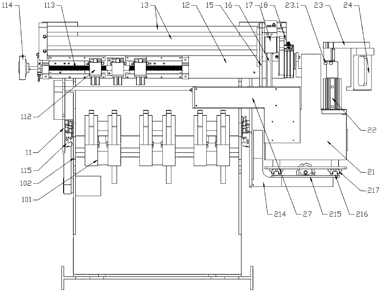
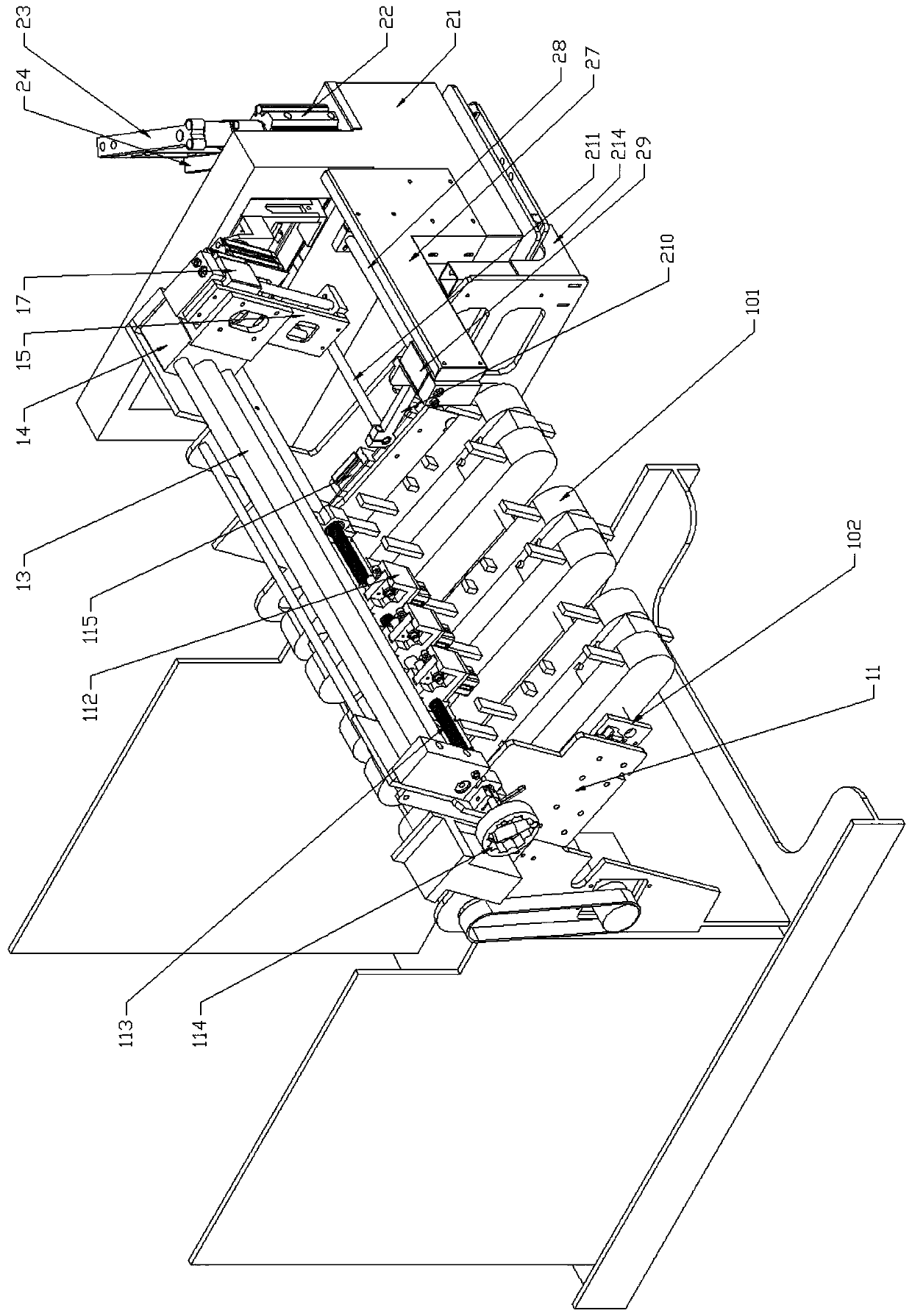
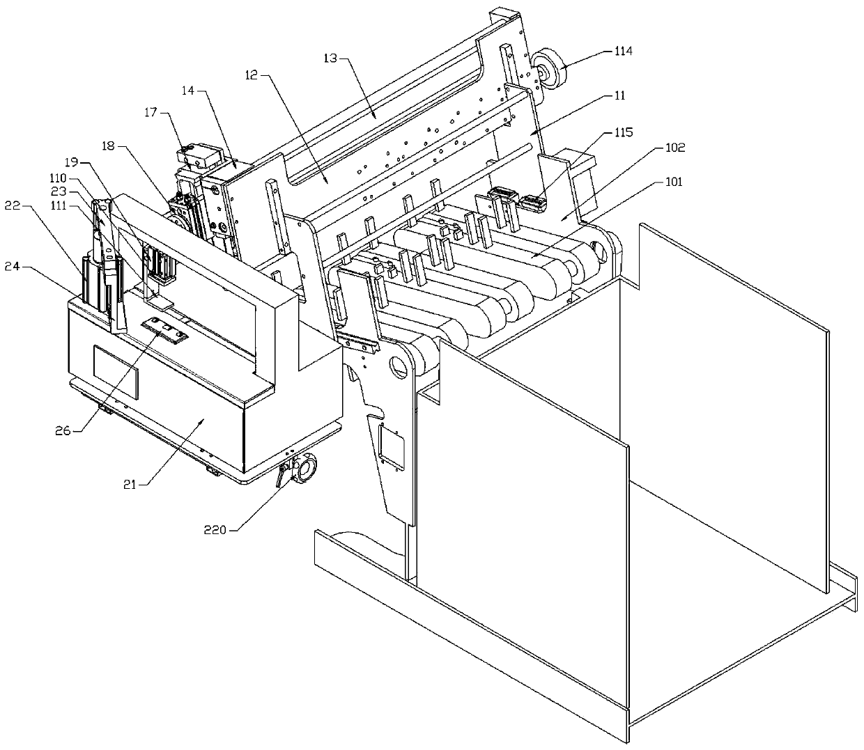
[0039] Embodiment one: if figure 1 - As shown in 6, a grabbing and binding mechanism of a bag unscrambling machine, including a grabbing mechanism and a binding mechanism, is installed at the rear of the bag unscrambling machine. The structure at the rear of the bag unscrambling machine includes several finishing assemblies 101 and two For the finishing wallboard 102 , the material-grabbing mechanism includes a material-grabbing wallboard 11 installed outside the finishing wallboard 102 , and the material-grabbing wallboard 11 and the finishing wallboard 102 are connected by a slider guide rail assembly 115 . A translation installation plate 12 is arranged between the grasping wallboards 11, and a plurality of translation guide shafts 13 are arranged on the translation installation plate 12. A translation cylinder 14 is provided on the translation guide shaft 13, and a lifting installation plate 15 is provided on the translation cylinder 14. Mounting plate 15 is provided with ...

Embodiment 2

[0041] Embodiment two: combine Figure 4-8 As shown, on the basis of Embodiment 1, a limit assembly is added to the grabbing mechanism to limit the movement of the translation cylinder 14 when grabbing materials. The translation mounting plate 12 is provided with a screw rod 113 and a stopper 112. The outer end of screw mandrel 113 is provided with handwheel 114, and limiter 112 includes limit mounting seat 112.1 and limit cylinder 112.2, and the cylinder movable rod 112.3 of limit cylinder 112.2 is connected limit slide block 112.4, and set limit slide block 112.4 The limit sensor 112.5, the limit mounting seat 112.1 is provided with the slider groove 112.1.1 for accommodating the limit slider 112.4 and the hole 112.1.2 for the screw rod 113 to pass through, and the limit mounting seat 112.1 rear portion is provided with a guide block 112.1.3. Wherein, the middle of the screw rod 113 is the optical axis, the number of stoppers 112 is three, the middle stopper 112 is located ...

Embodiment 3

[0042] Example Three: Combining Figure 9-13 As shown, on the basis of Embodiment 1 or Embodiment 2, a pusher assembly and an upper support assembly are added to the strapping mechanism. The pusher assembly is located inside the strapping machine 21 and includes a pusher mounting plate 27 connected to the strapping machine 21. Pushing material installation plate 27 is provided with some horizontal pushing material guide shafts 28, and pushing material translational cylinder 29 is provided on pushing material guiding shaft 28, and pushing material translational cylinder 29 is provided with rotating mounting plate 213, and rotating mounting plate 213 is provided with There is a material pushing rotary cylinder 212, which is connected to one end of the rocking arm 210, and the other end of the rocking arm 210 is provided with a push rod 211.

[0043] combine Figure 10-17 As shown, the upper support assembly is located outside the strap groove 21.1, and includes the upper suppor...


PUM


Abstract

A material grabbing and strapping mechanism of a bag management machine comprises a material grabbing mechanism and a strapping mechanism which are installed on the rear portion of the bag managementmachine. The material grabbing mechanism comprises material grabbing wallboards. A horizonal movement installation plate is arranged between the material grabbing wallboards. Horizontal movement guideshafts are arranged on the horizontal movement installation plate. A horizontal movement cylinder is arranged on the horizontal movement guide shafts. A lifting installation plate is arranged on thehorizontal movement cylinder. Lifting guide shafts are arranged on the lifting installation plate. A lifting cylinder is arranged on the lifting guide shafts. A rotation cylinder is arranged on the lifting cylinder. A material grabbing cylinder is arranged on the rotation cylinder. The movable end of the material grabbing cylinder is connected with an upper material grabbing plate. A lower material grabbing plate is arranged on one side of the material grabbing cylinder. The strapping mechanism comprises a strapping machine. A strapping tape groove is formed in a work table of the strapping machine. A strapping cylinder is arranged outside the strapping tape groove. The movable end of the strapping cylinder is connected with one end of a transverse rod, and the other end of the strapping cylinder is connected with a pressing block. The material grabbing and strapping mechanism can be well connected with a bag manufacturing and managing machine to achieve rapid strapping of packaging bags, the automation degree is high, and the labor cost is greatly reduced.

Description

technical field [0001] The invention relates to the technical field of packaging bag production and manufacturing equipment, in particular to a material grabbing and binding mechanism of a bag unscrambling machine. Background technique [0002] After the packaging bag is manufactured by the bag making machine and stacked by the bag unscrambler, it enters the binding process. The production speed of the existing bag making machine and bag unscrambler is very fast. If this process is manually operated, the efficiency is low and the cost is high. It cannot match the production speed of the bag making machine. [0003] In addition, the packaging bags from the bag making machine and bag unscrambling machine may be output in one or more ways according to different raw materials. The size and thickness of the packaging bags also have various specifications. To complete the bundling on the bundling machine, whether it is manual operation or the previous equipment operation (usually...

Claims


Application Information

Patent Timeline
IPC IPC(8): B65B35/16B65B13/02
CPCB65B13/02B65B35/16
Inventor 蔡永斌蒋武林
Owner 浙江创派智能科技有限公司
Why Eureka
Try Eureka