
Side plate tape winding machine

A technology of tape winding machine and side plate, applied in the direction of heating element shape and other directions, can solve the problems of unfavorable rapid production, large labor workload and high labor cost, and achieve the effect of reducing labor cost, consistent product quality and improving efficiency.

Active Publication Date: 2020-04-17
珠海锦至自动化设备有限公司
View PDF13 Cites 0 Cited by
  • Summary
  • Abstract
  • Description
  • Claims
  • Application Information

AI Technical Summary

Problems solved by technology

At this stage, winding heating belts for larger-sized side panels still needs to be done manually. The workload is heavy, the efficiency is low, and the labor cost is high, which is not conducive to large-scale and rapid production.

Method used


Image

  • Side plate tape winding machine
  • Side plate tape winding machine
  • Side plate tape winding machine

Examples


Embodiment Construction

[0024] Embodiments of the present invention are described in detail below, examples of which are shown in the drawings, wherein the same or similar reference numerals designate the same or similar elements or elements having the same or similar functions throughout. The embodiments described below by referring to the figures are exemplary only for explaining the present invention and should not be construed as limiting the present invention.

[0025] In the description of the present invention, it should be understood that the orientation descriptions, such as up, down, front, back, left, right, etc. indicated orientations or positional relationships are based on the orientations or positional relationships shown in the drawings, and are only In order to facilitate the description of the present invention and simplify the description, it does not indicate or imply that the device or element referred to must have a specific orientation, be constructed and operated in a specific ...


PUM


Abstract

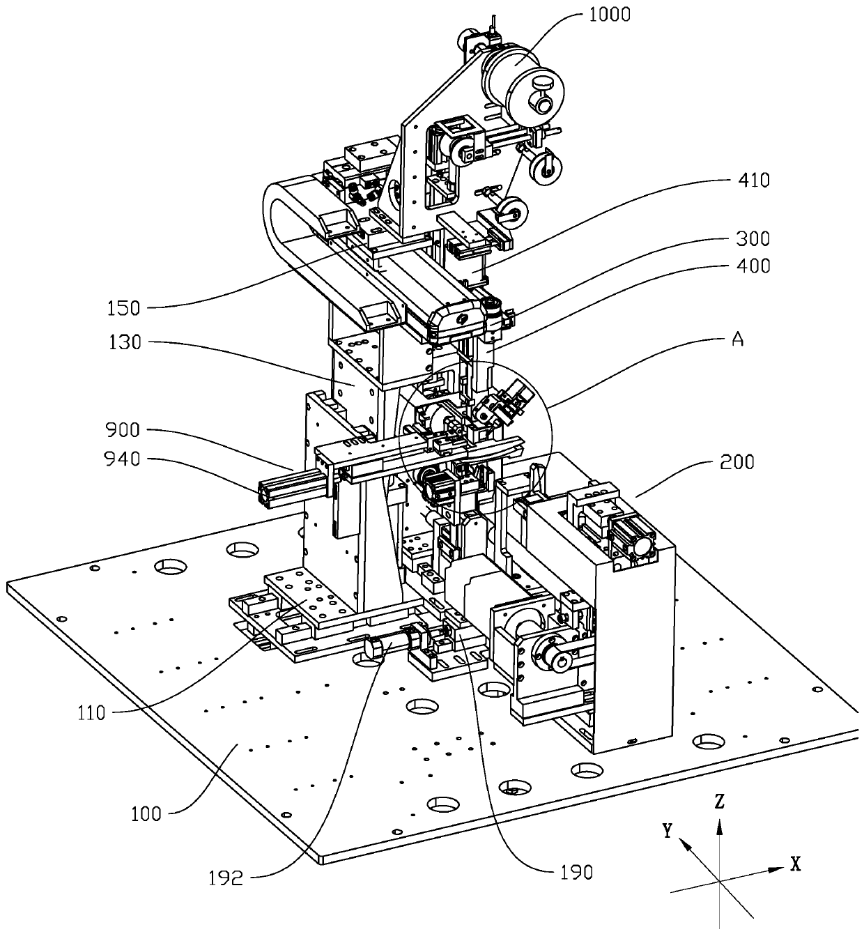
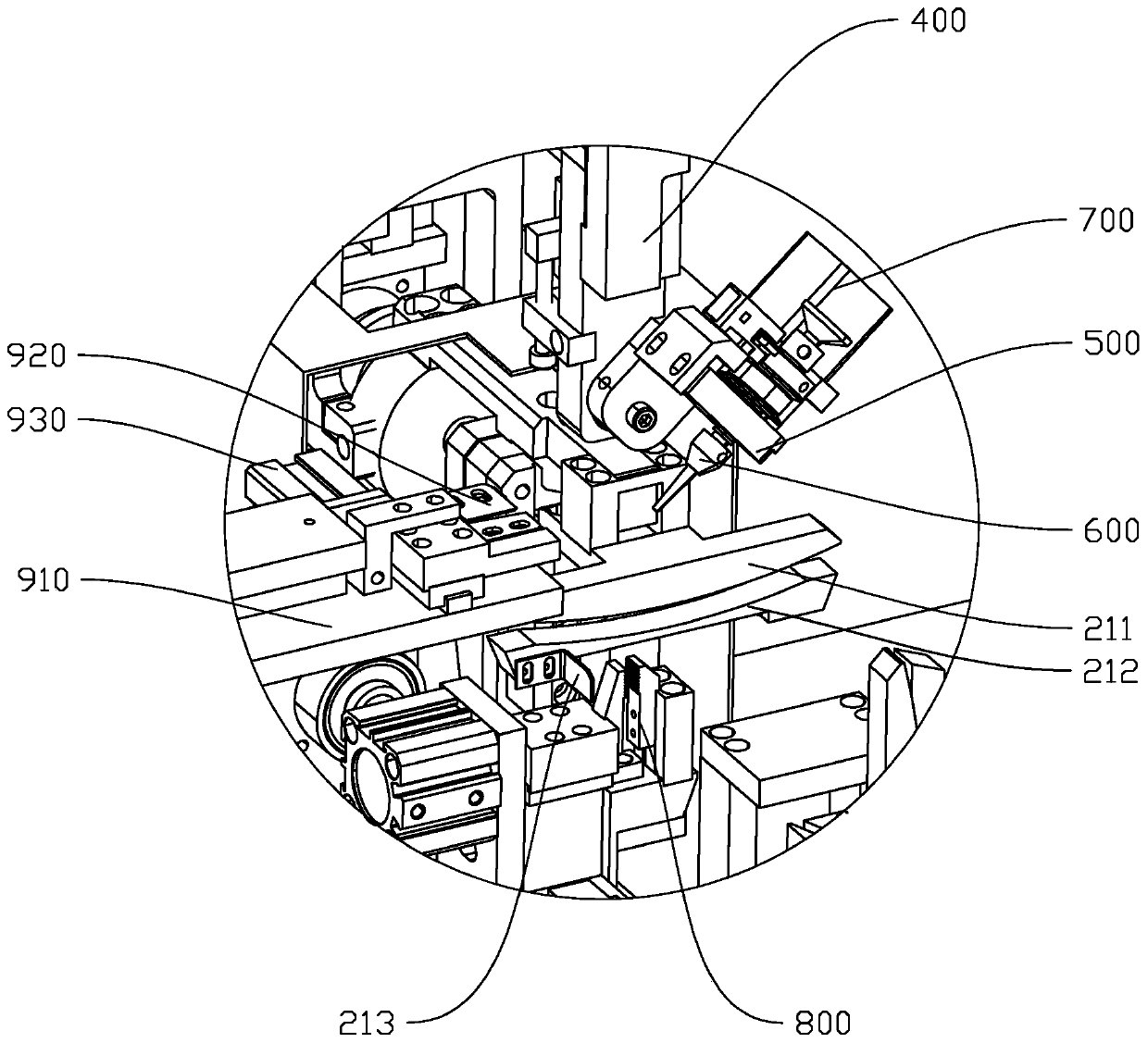
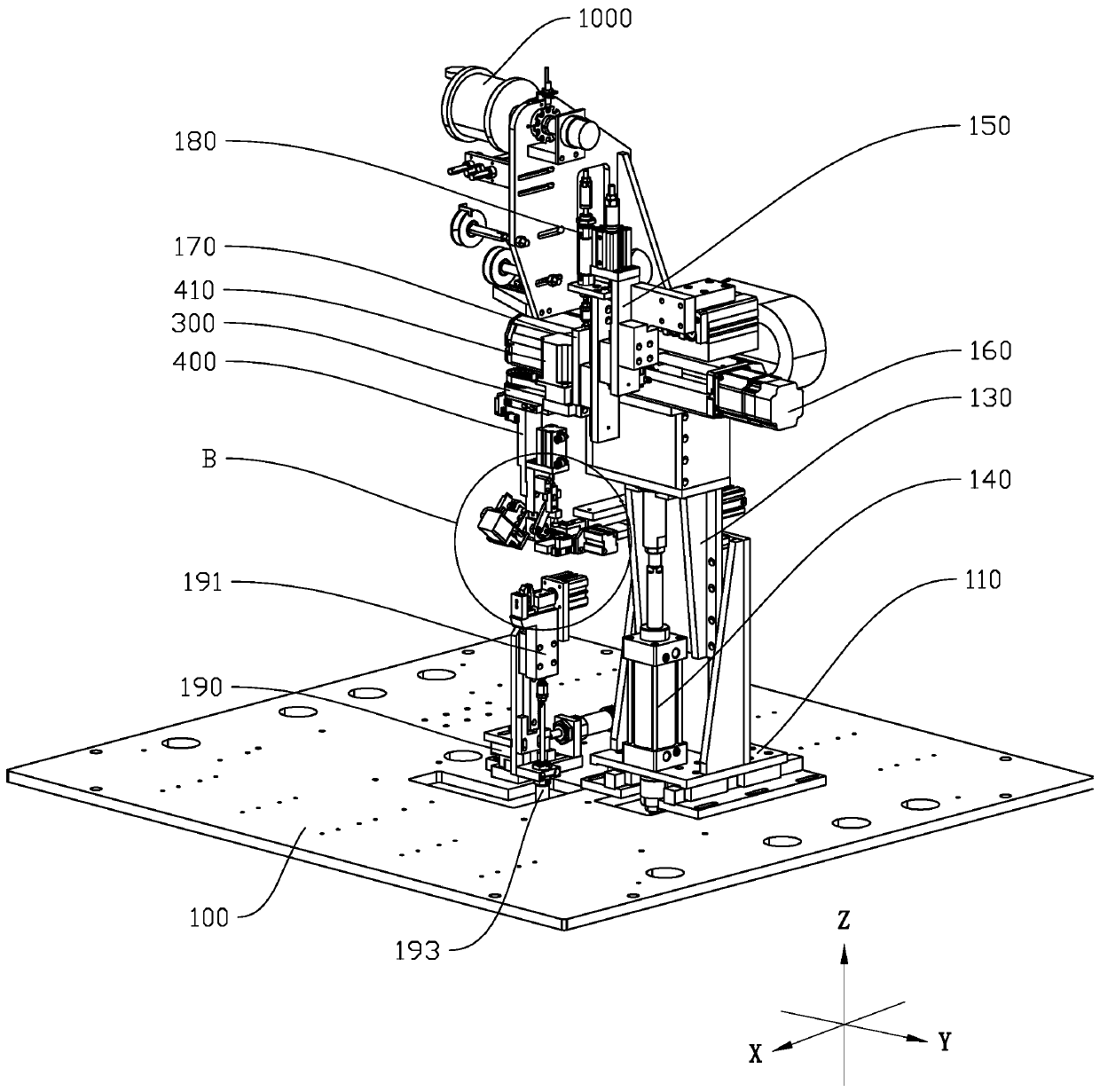
The invention discloses a side plate tape winding machine which comprises a bottom plate, a tape pulling clamp used for clamping a heating tape is further arranged on the bottom plate, and the tape pulling clamp can slide in the X-axis direction and the Z-axis direction. A clamping mechanism is arranged on the bottom plate and comprises a clamping head capable of rotating along the X axis, and theclamping head is used for clamping the side plate and the end of the heating tape. A connecting plate is arranged on the bottom plate and can slide in the X-axis direction, the Y-axis direction and the Z-axis direction. A supporting frame is arranged on the connecting plate, and a first rotary driving device drives the supporting frame to rotate around the Z-axis direction; a mounting plate is arranged on the supporting frame, and a second rotary driving device drives the mounting plate to rotate around the X-axis direction; a tape outlet head is arranged on the mounting plate and connected with a third rotary driving device, the third rotary driving device can drive the tape outlet head to rotate, and the tape outlet head is used for guiding the heating tape to be wound around the side plate. The side plate tape winding machine can replace manpower, reduce the labor cost, improve the efficiency of winding the heating tape, and meet the production of large-batch products.

Description

technical field [0001] The invention relates to the technical field of food processing equipment, in particular to a side plate winding machine. Background technique [0002] During food processing, it is often necessary to heat the food. The general heating methods include microwave heating or oven baking, etc. According to the energy used, there are electric heating and gas heating. In addition to microwave, electric heating can also use electric heating wire. The electric heating wire is also set in a strip shape, so the electric heating wire can also be called heating belt or heating wire. In order to heat the food evenly, the electric heating wire is usually Or the heating band is evenly dispersed and wound on the columnar or plate-shaped side plate. The corresponding two ends of the side plate are provided with slots for accommodating the heating band. After the heating band is wound on the two slots at the same end, the heating band is wound to the other end, and the...

Claims


Application Information

Patent Timeline
Patent Type & Authority Applications(China)
IPC IPC(8): H05B3/54
CPCH05B3/54
Inventor 疏龙标刘贻敏
Owner 珠海锦至自动化设备有限公司
Learn More