
Cathode assembly having a dual position magnetron and centrally fed coolant

A magnetron and coolant technology, applied in the field of magnetron, can solve the problems of laborious chamber, changing power, etc.

Active Publication Date: 2020-04-17
APPLIED MATERIALS INC
View PDF19 Cites 0 Cited by
  • Summary
  • Abstract
  • Description
  • Claims
  • Application Information

AI Technical Summary

Problems solved by technology

However, changing the power is laborious and requires constant monitoring of the deposition rate of the chamber

Method used


Image

  • Cathode assembly having a dual position magnetron and centrally fed coolant
  • Cathode assembly having a dual position magnetron and centrally fed coolant

Examples


Embodiment Construction

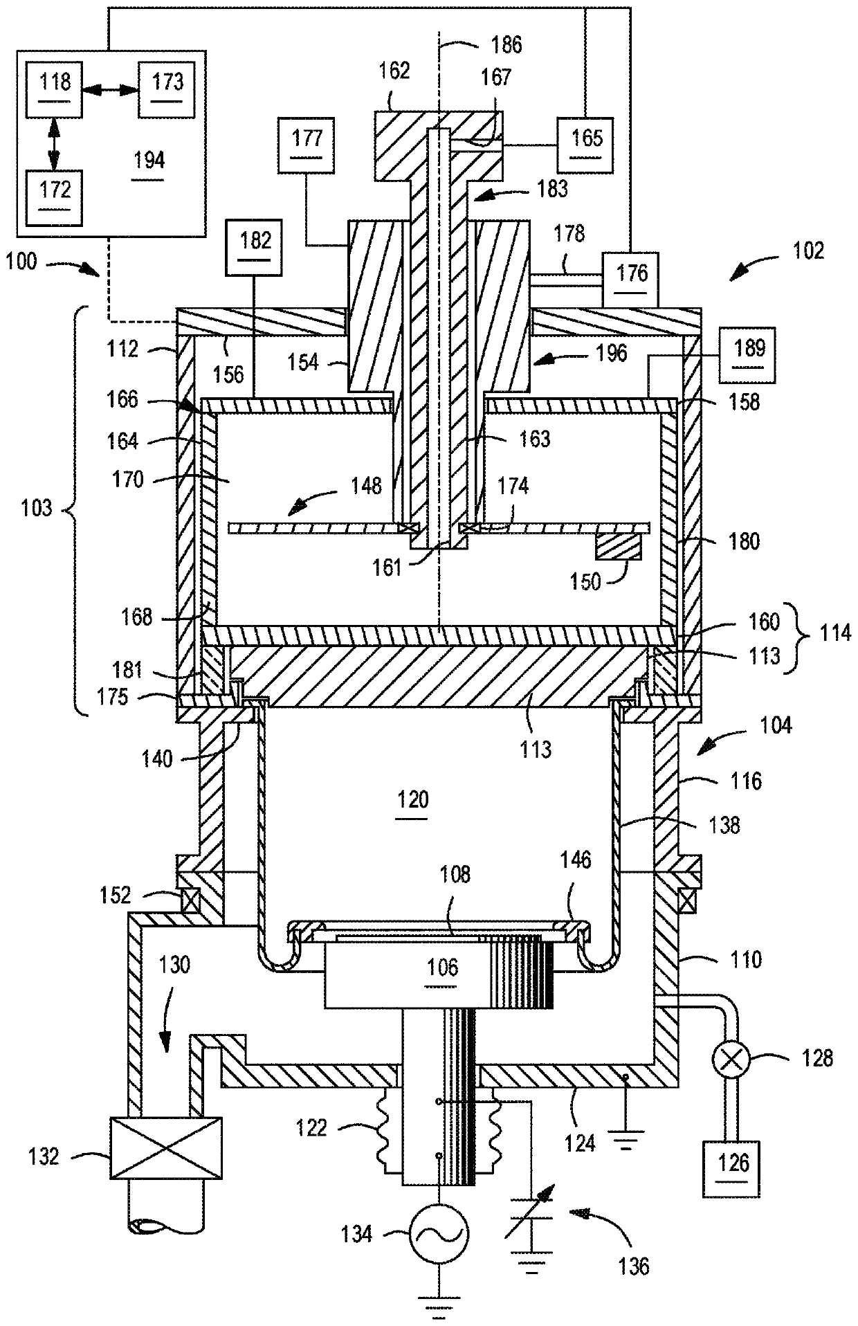
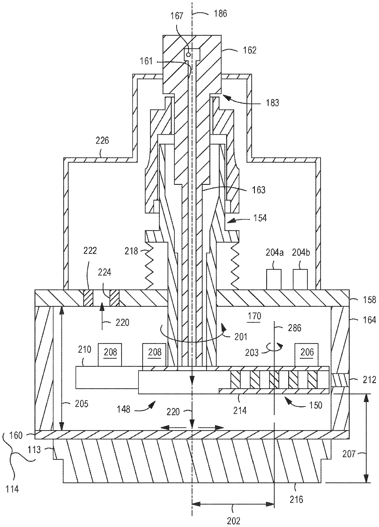
[0015] The present disclosure relates to a cathode assembly having a two-position magnetron that can advantageously utilize a centralized supply of coolant for improved cooling and that can be achieved by both in the deposition process and in the physical The distance between the lowermost surface of the magnet of the magnetron and the lowermost surface of the sputtering target is kept constant during the vapor deposition (PVD) chamber to ensure a constant deposition rate. The magnetron of the present invention advantageously mitigates cracking and / or bowing of the target due to overheating and decreases in deposition rate over the lifetime of the target.

[0016] Embodiments of the magnetron disclosed herein have two positions (an outer radial position and an inner radial position) so that the magnetic field at the sputter target surface can be changed by reconfiguring the magnetic poles at different positions. Therefore, since both the center and the periphery of the target ...


PUM


Abstract

Embodiments of a magnetron assembly and a processing system incorporating same are provided herein. In some embodiments, a magnetron assembly includes a body extending along a central axis of the magnetron assembly; a coolant feed structure extending through the body along the central axis to provide a coolant along the central axis to an area beneath the coolant feed structure; and a rotatable magnet assembly coupled to a bottom of the body and having a plurality of magnets. In some embodiments, the rotatable magnet assembly is configured to move vertically.

Description

technical field [0001] Embodiments of the present disclosure generally relate to magnetrons used in physical vapor deposition chambers for substrate processing. Background technique [0002] Sputtering, or physical vapor deposition (PVD), has long been used to deposit metals and related materials in the fabrication of semiconductor integrated circuits. The use of PVD has expanded to deposit metal layers onto the sidewalls of high aspect ratio holes, such as vias or other vertical interconnect structures. Currently, advanced sputtering applications include depositing materials with high stress and high ion density into these vias. [0003] For example, titanium, tantalum, etc. have been used in through silicon via (TSV) applications. The inventors have observed that in such applications utilizing highly stressed target materials and thus high power, due to high target temperature and insufficient cooling, the target starts to crack and buckle. Although coolant has been use...

Claims


Application Information

Patent Timeline
IPC IPC(8): H01J37/34
CPCC23C14/35C23C14/3407C23C14/345H01J37/3455H01J37/3405H01J37/3497H01J37/347H01J37/3408H01J37/3435H01J37/3426
Inventor 艾琳娜·H·威索克希兰库玛·萨万戴亚安东尼·陈志东宋焦帕拉沙特·帕布
Owner APPLIED MATERIALS INC
Learn More