
Mounting structure and nanoparticle mounting material

A technology of nano-particles and installation materials, which is applied in the direction of nano-technology, nano-technology, and nano-technology for information processing. The effect of suppressing generation

Pending Publication Date: 2020-04-17
PANASONIC INTELLECTUAL PROPERTY MANAGEMENT CO LTD
View PDF1 Cites 0 Cited by
  • Summary
  • Abstract
  • Description
  • Claims
  • Application Information

AI Technical Summary

Problems solved by technology

However, if the above-mentioned temperature at the time of sintering is increased, thermal damage will occur to peripheral members exposed to high temperature during sintering.
On the other hand, if the holding temperature during bonding is kept low to suppress thermal damage to peripheral members, the time required for the above-mentioned heating process will increase exponentially, and the cost will increase especially in mass production.
In this way, if it is desired to bond the element electrode and the lead frame electrode through the sintering of the above-mentioned nanoparticle mounting material, it is difficult to simultaneously suppress thermal damage to peripheral components, improve the quality of the product, and shorten the lead time for mass production. ) to curb the cost of both

Method used


Image

  • Mounting structure and nanoparticle mounting material
  • Mounting structure and nanoparticle mounting material
  • Mounting structure and nanoparticle mounting material

Examples


Embodiment 1

[0060] 1. Fabrication of installation structure

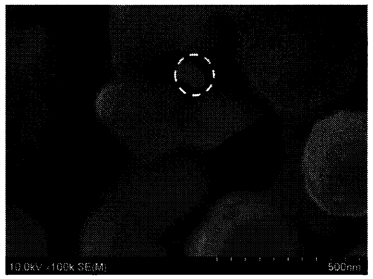
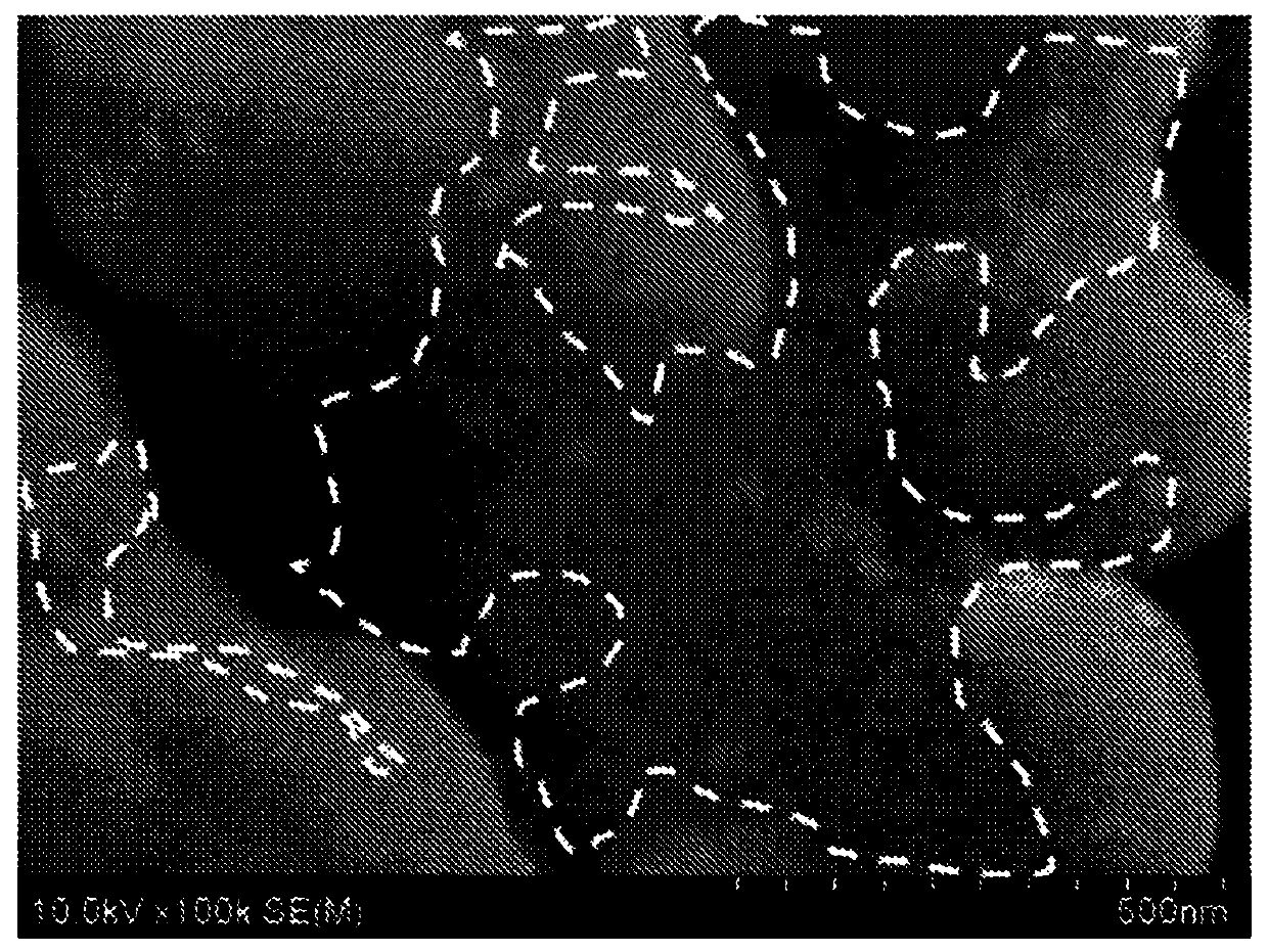
[0061] Separately, prepare Ag nanoparticles with an average particle diameter of 100 nm as nanoparticles of the first metal, prepare Sn nanoparticles with an average particle diameter of 100 nm, Sb nanoparticles with an average particle diameter of 100 nm, and Pd nanoparticles with an average particle diameter of 100 nm. Nanoparticles, come as nanoparticles of the second metal. When the nanoparticles of the first metal were observed with a scanning electron microscope (SEM), the ratio of nanoparticles having a particle size of 100 nm or less was 50% relative to the number of observed nanoparticles of the first metal.

[0062] The total amount of nanoparticles of the first metal and nanoparticles of the second metal is 70% by mass, the amount of polyethylene glycol (average molecular weight is 200) as the organic solvent is 29% by mass, and the amount of the dispersant and the reducing agent is The total amount was 1% by mass, ...

Embodiment 2

[0087] In Example 2, except having used Cu, Pb, and Ge as the second metal, it carried out similarly to Example 1, and produced and evaluated the mounting structure.

[0088] In addition, the diffusion coefficient of Cu in Ag at 200°C is 10 -17 m 2 On the order of / sec, the diffusion coefficient of Pb in Ag at 200°C is 10 -22 m 2 On the order of / sec, the diffusion coefficient of Ge in Ag at 200°C is 10 -22 m 2 The magnitude of / sec. Each of these diffusion coefficients is greater than the self-diffusion coefficient of Ag in Ag at 200°C.

[0089] In addition, the compounding ratio of the nanoparticles of the second metal is adjusted so that the mass of Cu, Pb, and Ge relative to the total mass of Ag becomes half of the solid solution limit at 200°C in the equilibrium diagram of Ag and each element .

[0090] Table 2 shows the types of the first metal and the second metal in Example 2, and the second metal relative to the total mass of the nanoparticles of the first meta...

Embodiment 3

[0097] In Example 3, except having used Cu as the first metal and Ge as the second element, it carried out similarly to Example 1, and produced and evaluated the mounting structure.

[0098] In addition, the diffusion coefficient of Ge in Cu at 200°C is 10 -23 m 2 On the order of / sec, the self-diffusion coefficient of Cu in Cu at 200°C is 10 -29 m 2 The magnitude of / sec. The diffusion coefficient of Ge in Cu at 200°C is larger than the self-diffusion coefficient of Cu in Cu at 200°C.

[0099] In addition, the compounding ratio of the nanoparticles of the second metal (Ge) was adjusted so that the mass of Ge relative to the total mass of Cu was half of the solid solution limit at 200° C. in the equilibrium diagram of Cu and Ge.

[0100] Table 3 shows the types of the first metal and the second metal in Example 3, and the second metal relative to the total mass of the nanoparticles of the first metal (Cu) and the nanoparticles of the second metal (Ge). The mass ratio (con...


PUM

PropertyMeasurementUnit
particle sizeaaaaaaaaaa
particle diameteraaaaaaaaaa

Abstract

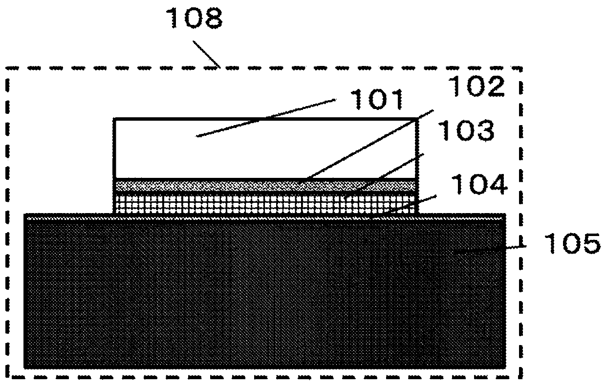
The present invention uses a mounting structure which comprises: a semiconductor element that has an element electrode; a metal member; and a sintered body which bonds the semiconductor element and the metal member with each other. This mounting structure is configured such that: the sintered body contains a first metal and a second metal that is solid-solved in the first metal; the diffusion coefficient of the second metal in the first metal is higher than the self-diffusion coefficient of the first metal; and the content of the second metal with respect to the total mass of the first metal and the second metal in the sintered body is not more than the solid solubility limit of the second metal in the first metal.

Description

technical field [0001] The present invention relates to a mounting structure having a structure in which two members are joined by a metal material used in equipment such as a power plant, and a nanoparticle mounting material used in its manufacture. Background technique [0002] Equipment with semiconductor elements that generate heat, such as power plants, may carry out heat transfer from the substrate on which the semiconductor elements are mounted to the heat dissipation part for the purpose of dissipating the heat generated by the semiconductor elements. An installation structure obtained by joining two components. [0003] In recent years, from the viewpoint of energy saving, the use of next-generation power plant elements such as SiC elements and GaN elements, which have the advantage of being able to control electric power efficiently, has been increasing from existing Si elements. These next-generation power plant elements have the advantage of being able to operat...

Claims


Application Information

Patent Timeline
Patent Type & Authority Applications(China)
IPC IPC(8): H01L21/52B22F7/08B82Y10/00C22C5/06C22C9/00B22F1/054B22F1/10
CPCB22F7/08C22C9/00B82Y10/00C22C5/06H01L21/52B22F7/064B22F2999/00H01L24/29H01L24/32H01L2224/32245H01L2224/8384H01L2224/8321H01L24/83H01L2224/04026H01L2224/29316H01L2224/29339H01L2224/29347H01L2224/29317H01L2224/05644H01L2224/29311H01L2224/29294B22F1/10B22F1/054H01L2924/01032H01L2924/00014C22C1/0466C22C1/0425C22C1/0483H01L2224/29239H01L2224/29247H01L2924/3651
Inventor 日根清裕北浦秀敏古泽彰男
Owner PANASONIC INTELLECTUAL PROPERTY MANAGEMENT CO LTD
Learn More