Aluminum material cutting device with automatic feeding function

A technology for automatic feeding and cutting devices, applied in the direction of shearing devices, attachments of shearing machines, maintenance and safety accessories, etc., to achieve the effect of avoiding poor air quality

Active Publication Date: 2020-04-21
重庆市金久装饰工程有限责任公司
View PDF7 Cites 3 Cited by
  • Summary
  • Abstract
  • Description
  • Claims
  • Application Information

AI Technical Summary

Problems solved by technology

[0003] The present invention intends to provide an automatic feeding aluminum material cutting device to solve the technical problem that the prior art cannot automatically feed and cut aluminum materials

Method used


Image

  • Aluminum material cutting device with automatic feeding function
  • Aluminum material cutting device with automatic feeding function
  • Aluminum material cutting device with automatic feeding function

Examples


Embodiment 1

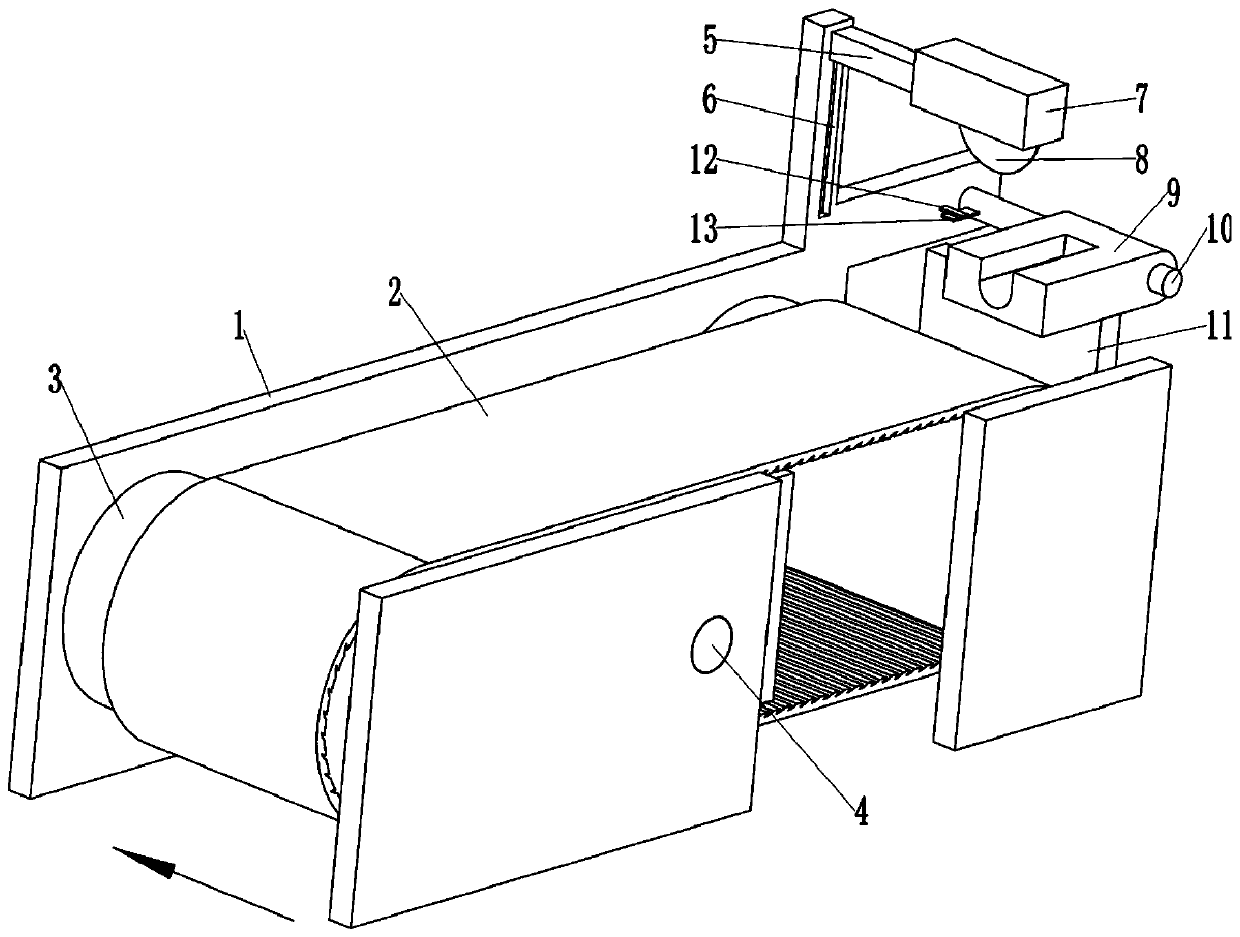
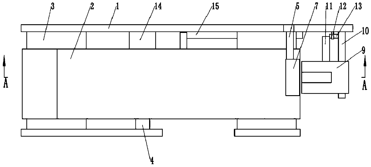
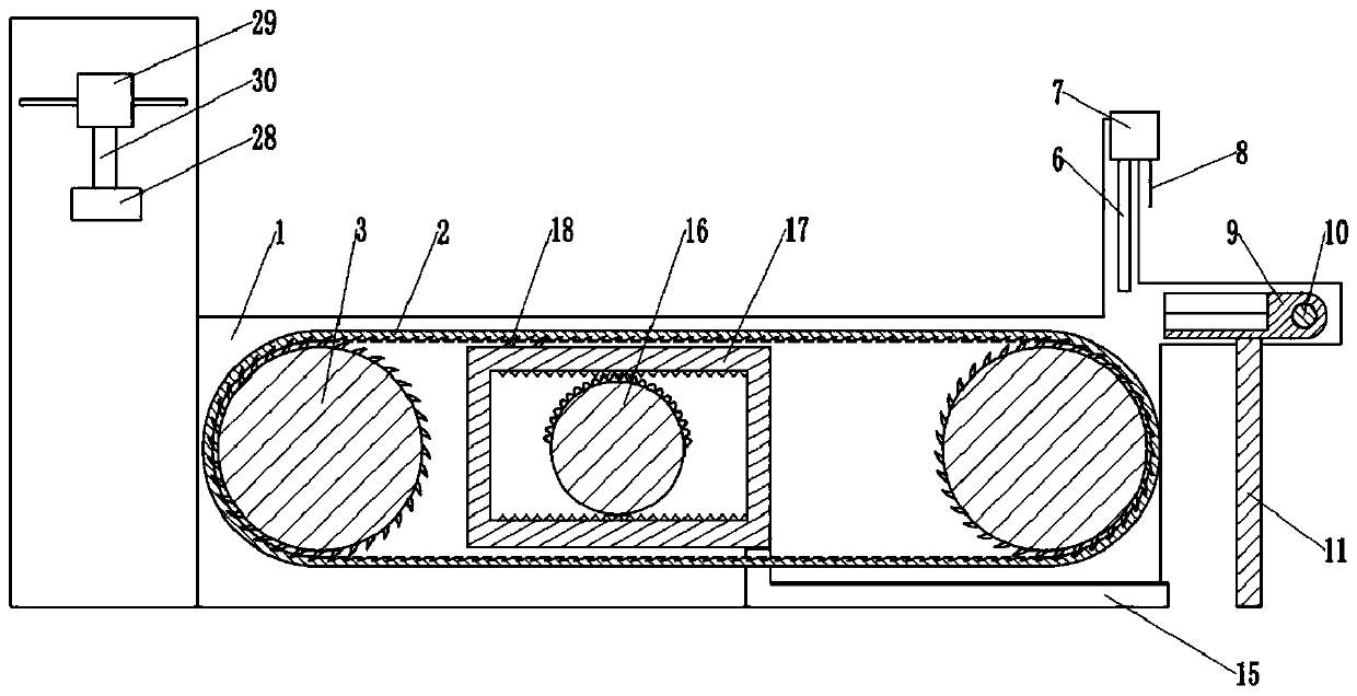
[0033] as attached figure 1 Shown: an automatic feeding aluminum material cutting device, including a frame 1 and a feeding unit, the feeding unit includes a conveyor belt 2 and a driving structure for driving the conveyor belt 2, and the conveyor belt 2 is stretched directly on the frame 1, specifically as image 3 As shown, there are two cross bars 3 clamped and fixedly connected to the frame 1 , the longitudinal section of the cross bars 3 is circular, and the conveyor belt 2 is stretched straight on the two cross bars 3 . Such as image 3 As shown, the driving structure is arranged in the conveyor belt 2, the driving structure includes a driving gear 16 and a rectangular frame 17, the rectangular frame 17 is horizontally slidably connected with the frame 1 through a chute, and the top and bottom of the inner peripheral surface of the rectangular frame 17 are clamped and fixed. There is a rack, and the driving gear 16 is an incomplete gear, and the driving gear 16 is meshe...

Embodiment 2

[0045] Such as Figure 4 As shown, the difference between this embodiment and Embodiment 1 is that the frame 1 is fixed with a seal box 19 by bolts, and a piston 20 is horizontally slid in the seal box 19, and the left end of the piston 20 is clamped and fixedly connected with a piston rod 21. The piston rod 21 is clamped and fixed with the rectangular frame 17 . The piston 20 separates the sealed box 19 into a first sealed space 26 and a second sealed space 27, the first sealed space 26 is communicated with a first hose 22, the second sealed space 27 is communicated with a second hose 23, and the second sealed space 27 is communicated with a second hose 23. The position where the flexible pipe 23 communicates with the sealed box 19 is located at the top of the sealed box 19; Figure 5 As shown, the support member 9 is provided with an air blow hole 24, and the upper end of the air blow hole 24 is inclined to the left, so that the airflow blown out by the air blow hole 24 is ...


PUM


Abstract

The invention relates to the technical field of aluminum material machining equipment, and discloses an aluminum material cutting device with an automatic feeding function. The aluminum material cutting device comprises a rack and a feeding unit, wherein the feeding unit comprises a conveying belt and a driving structure used for driving the conveying belt, wherein the conveying belt is straightened and arranged on the rack, the driving structure is arranged in the conveying belt, the driving structure comprises a driving gear and a rectangular frame, the rectangular frame is slidably connected with the rack, a rack is arranged in the rectangular frame, the driving gear is an incomplete gear, the driving gear is rotatably connected with the rack, and the driving gear is engaged with the rack; and a one-way locking piece for one-way clamping is arranged between the rectangular frame and the conveying belt. The scheme of the invention can solve the technical problem that aluminum materials cannot be automatically fed and cut in the prior art.

Description

technical field [0001] The invention relates to the technical field of aluminum material processing equipment, in particular to an automatic feeding aluminum material cutting device. Background technique [0002] Aluminum processing involves various processing techniques such as cutting and grinding. Cutting refers to cutting the aluminum into small pieces of required size. The existing technology needs to manually send the aluminum to the position of the cutting knife for cutting, sometimes even It is necessary to manually hold the aluminum material for cutting, which leads to a particularly large potential safety hazard for workers. Many equipments with automatic feeding and automatic cutting are also disclosed in the prior art, but most of them are controlled by numerical control machine tools, resulting in high production cost and use cost of the equipment, and professional training for workers is required before use, resulting in The time cost and labor cost invested a...

Claims


Application Information

Patent Timeline
Patent Type & Authority Applications(China)
IPC IPC(8): B23D19/00B23D33/02B23Q11/10
CPCB23D19/00B23D33/02B23Q11/10
Inventor 刘玲蒋宇宏杨洋
Owner 重庆市金久装饰工程有限责任公司
Why Eureka
Try Eureka