Robot finger joint
A technology of robot fingers and joints, applied in the direction of manipulators, chucks, manufacturing tools, etc., can solve the problems of inability to perform length, incompletion, complex movements, etc., and achieve good adjustment effects, good rotation effects, and good telescopic effects.
- Summary
- Abstract
- Description
- Claims
- Application Information
AI Technical Summary
Problems solved by technology
Method used
Image
Examples
Embodiment 1
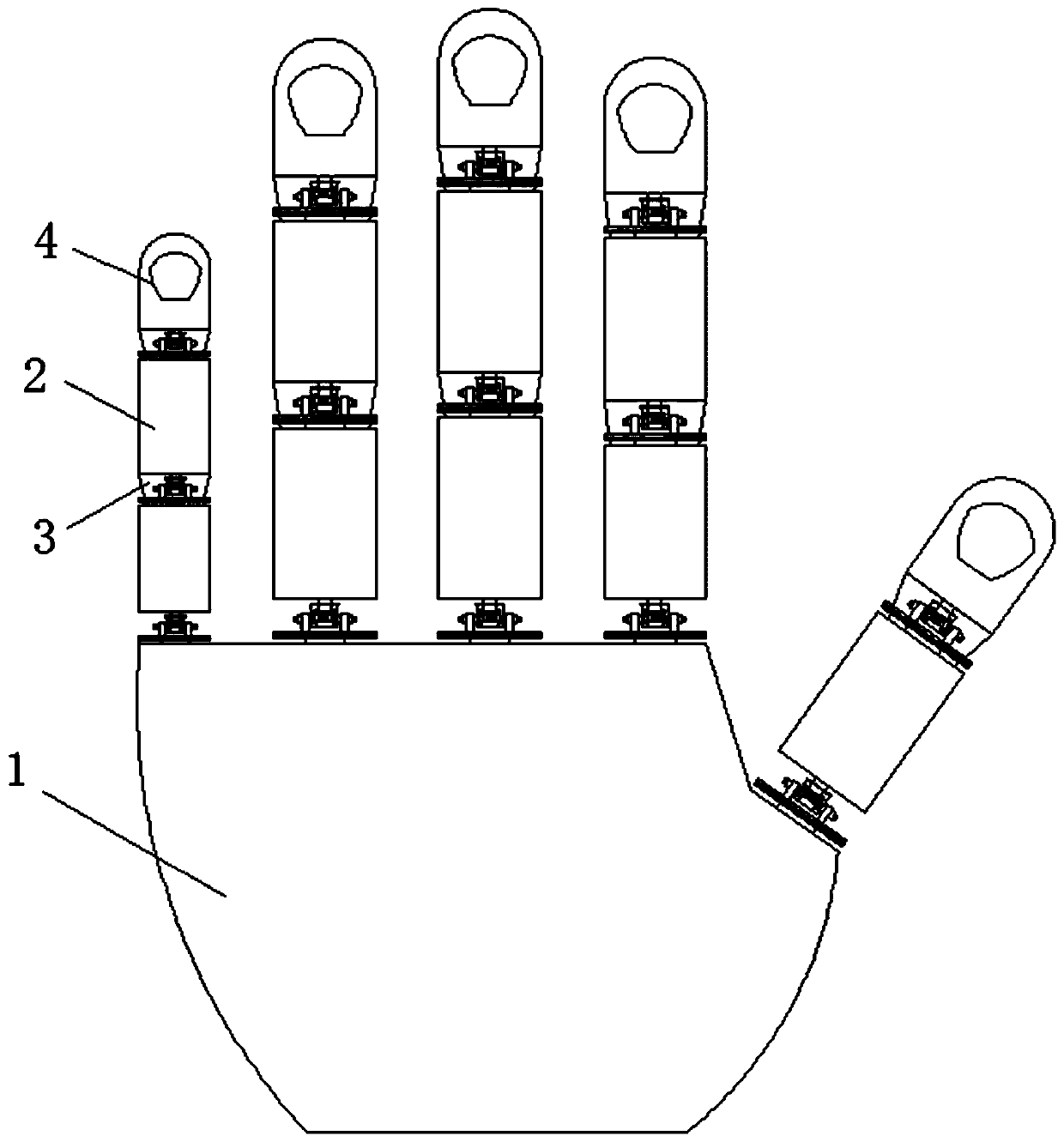
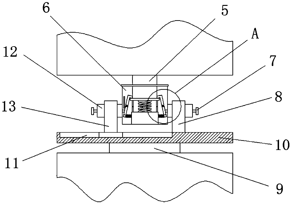
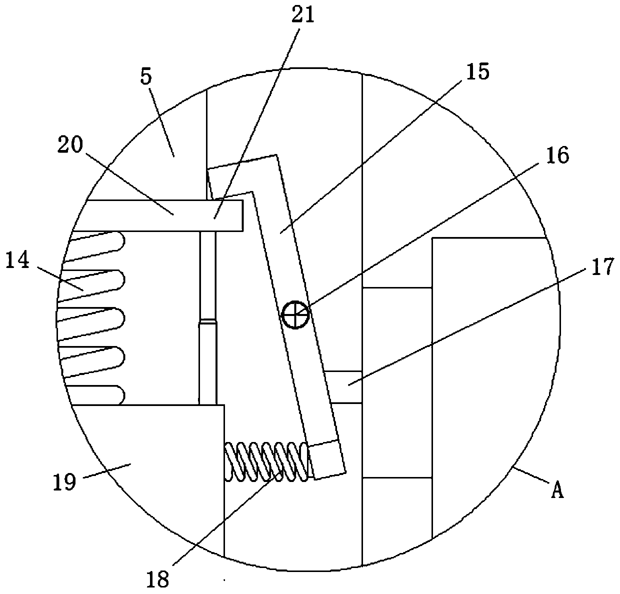
[0030] see Figure 1-4 , this embodiment provides a robot finger joint, including a palm body 1, five fingers 2 are movably installed on the upper end of the palm body 1, knuckles 4 are arranged on the fingers 2, and a rotating The shaft 9 and the upper end of the rotating shaft 9 are fixedly connected with a mounting plate 10, one side of the upper end of the mounting plate 10 is fixedly connected with a fixed frame 8, and the other side of the upper end of the mounting plate 10 is movably installed with a movable frame 13, and the movable frame 13 and the fixed frame 8 are fixedly connected with connecting bolts 12, and the installation box 6 is fixedly connected between the connecting bolts 12. The two connecting bolts 12 are all inserted with pressing rods 17, and the connecting bolts 12 run through the connecting bolts 12 transversely. The middle part of the surface is fixedly connected with a mounting seat 19, and the middle part of the upper surface of the mounting seat...
Embodiment 2
[0033] see Figure 1-5 , on the basis of Embodiment 1, a further improvement has been made: one end of the pressing rod 17 is fixedly connected to the outside of the connecting bolt 12 with a push block 7, and the setting of the push block 7 facilitates the operation and use of the push rod 17, and the finger The lower end of one side of the surface of the joint 4 is fixedly connected with a shielding plate 3, and the shielding plate 3 has an inverted trapezoidal structure. Through the setting of the shielding plate 3, the knuckle 4 is prevented from bending to the other side of the palm main body 1, which affects the bending effect of the overall device. One side of the clamping frame 15 is fixedly connected with a back-moving spring 18, and the other end of the back-moving spring 18 is fixedly connected with the outer wall of the mounting seat 19, and the clamping frame 15 position is restored under the action of the back-moving spring 18.
PUM
 Abstract
Description
Claims
Application Information
 - R&D
- Intellectual Property
- Life Sciences
- Materials
- Tech Scout
- Unparalleled Data Quality
- Higher Quality Content
- 60% Fewer Hallucinations
Browse by: Latest US Patents, China's latest patents, Technical Efficacy Thesaurus, Application Domain, Technology Topic, Popular Technical Reports.
© 2025 PatSnap. All rights reserved.Legal|Privacy policy|Modern Slavery Act Transparency Statement|Sitemap|About US| Contact US: help@patsnap.com


