
Building insulation system

A technology for building insulation and air vents, applied in buildings, building components, building structures, etc., can solve the problems that cannot be solved fundamentally, the general dehumidification effect of the dehumidifier, the general drying effect of the wall, etc., to reduce the maintenance of dehumidification Cost, solve condensed water problem, ensure drying effect

Inactive Publication Date: 2020-04-21
山东斯诺尔节能建材有限公司
View PDF4 Cites 1 Cited by
  • Summary
  • Abstract
  • Description
  • Claims
  • Application Information

AI Technical Summary

Problems solved by technology

The first way desiccant needs to be replaced regularly, the operation is very troublesome, and the desiccant is easy to absorb water saturation, the wall drying effect is average; the second way needs to open the dehumidifier regularly to dehumidify, not only troublesome operation, but also for large-scale dehumidification, The dehumidification effect of the dehumidifier is average
The two methods not only cannot fundamentally solve the problem, but also have the problem of energy waste

Method used


Image

  • Building insulation system
  • Building insulation system
  • Building insulation system

Examples


Embodiment Construction

[0021] In order to clearly illustrate the technical features of the solution, the solution will be described below through specific implementation modes.

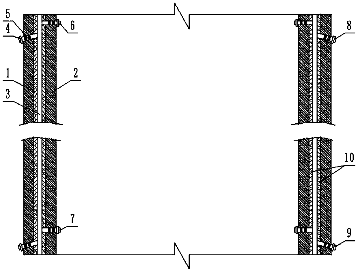
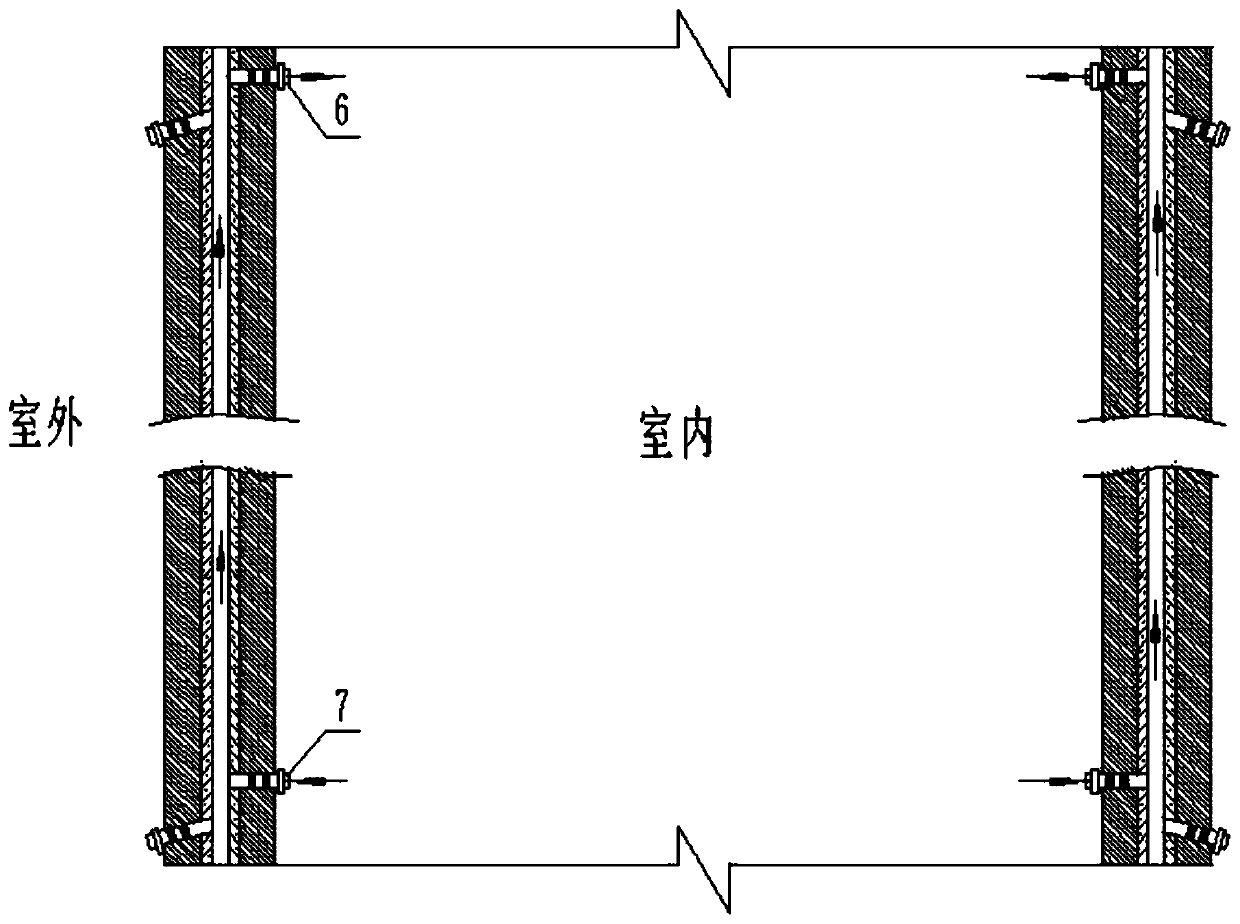
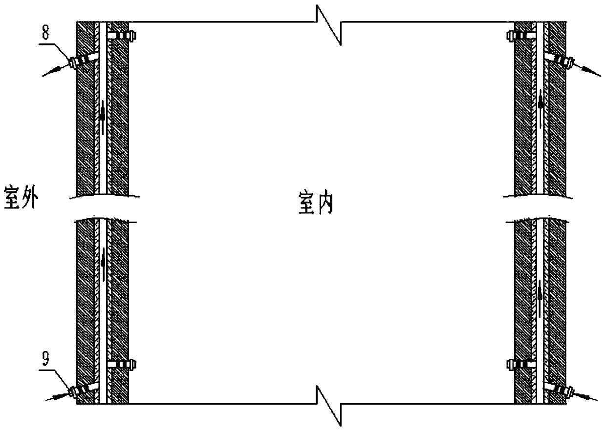
[0022] Such as figure 1 , 2 As shown, the present invention includes an outer wall 1 and an inner wall 2, and a cavity 3 is arranged between the outer wall 1 and the inner wall 2. The inner wall 2 is provided with a plurality of internal air vents connecting the indoor space with the cavity 3 , and the outer wall 1 is provided with a plurality of external air vents communicating with the outdoor room and the cavity 3 . An electric sealing valve 4 and a one-way valve 5 are installed in each inner vent and the outer vent.

[0023] The inner air vents include a plurality of upper inner air vents 6 and lower inner air vents 7 located at the upper and lower parts of the inner wall 2 respectively, and the outer air vents include a plurality of upper outer air vents located at the upper and lower parts of the outer wall 1 respec...


PUM


Abstract

The invention relates to a building insulation system. The building insulation system comprises an outer wall and an inner wall, wherein a cavity is formed between the outer wall and the inner wall; the inner wall is provided with a plurality of inner air vents communicating with an indoor place and the cavity, and the outer wall is provided with a plurality of outer air vents communicating with an outdoor place and the cavity; an electric closed valve and a one-way valve are installed in each inner air vent and each outer air vent; each inner air vent comprises a plurality of upper inner airvents and a plurality of lower inner air vents which are located at the upper portion and the lower portion of the inner wall correspondingly, and each outer air vent comprises a plurality of upper outer air vents and a plurality of lower outer air vents which are correspondingly located at the upper portion and the lower portion of the outer wall; the ventilation direction of the one-way valves in the upper inner air vents is opposite to that of the one-way valves in the lower inner air vents, and the ventilation direction of the one-way valves in the upper outer air vents is opposite to thatof the one-way valves in the lower outer air vents; the electric closed valves installed in the inner wall are opened in summer and closed in winter; and the electric closed valves installed in the outer wall are closed in summer and opened in winter. Generation of condensed water in the wall is avoided, and the problem of the condensed water is fundamentally solved.

Description

technical field [0001] The invention relates to the technical field of building heat preservation, in particular to a building heat preservation system. Background technique [0002] At present, the main factor affecting the service life of buildings is the condensed water inside the wall. The condensed water will cause the wooden structure of the building to rot, metal corrosion, paint, masonry and concrete to fall off, seriously affecting the life of the building. Condensed water originates from the building itself. In winter, when the indoor temperature is higher than the outdoor temperature, the air with higher indoor temperature passes through the inner wall and encounters the lower temperature outer wall, where condensation occurs on the inner wall of the outer wall. In summer, the indoor temperature is lower than the outdoor temperature, and the air with a higher outdoor temperature passes through the outer wall and meets the inner wall with a lower temperature, conde...

Claims


Application Information

Patent Timeline
Patent Type & Authority Applications(China)
IPC IPC(8): E04B1/70E04B2/00
CPCE04B1/7069E04B1/7076E04B1/7092E04B2/00
Inventor 王业贞王晓菡李秀荣
Owner 山东斯诺尔节能建材有限公司
Learn More