
Interlayer concave combined type unit curtain wall

A unit curtain wall and combined technology, which is applied in the direction of walls, building components, buildings, etc., can solve the problems of unguaranteed installation quality on site, many vertical decorative metal plate components, and difficulty in ensuring flatness, etc., so as to improve the overall economic benefits, Facilitate quality control and reduce potential safety hazards

Active Publication Date: 2020-04-21
BEIJING JANGHO CURTAIN WALL SYST ENG +1
View PDF11 Cites 0 Cited by
  • Summary
  • Abstract
  • Description
  • Claims
  • Application Information

AI Technical Summary

Problems solved by technology

[0002] In the prior art, the interlayer special-shaped curtain wall metal plate decorative strip curtain wall is generally designed according to the frame system, there are many vertical decorative metal plate components, the quality of on-site installation cannot be guaranteed, and the installation is complicated, the construction is difficult, the labor cost is high, and the installation period long
In addition, the above-mentioned technology does not have a complete waterproof system, and there are hidden dangers of water leakage. The splicing design of the transfer aluminum column adopts the splicing design after the core is connected and welded. The process is complicated, and the strength of the aluminum column is greatly reduced after welding, and the flatness is difficult to guarantee

Method used


Image

  • Interlayer concave combined type unit curtain wall
  • Interlayer concave combined type unit curtain wall
  • Interlayer concave combined type unit curtain wall

Examples


Embodiment Construction

[0025] Specific embodiments of the present invention will be described in detail below with reference to the accompanying drawings.

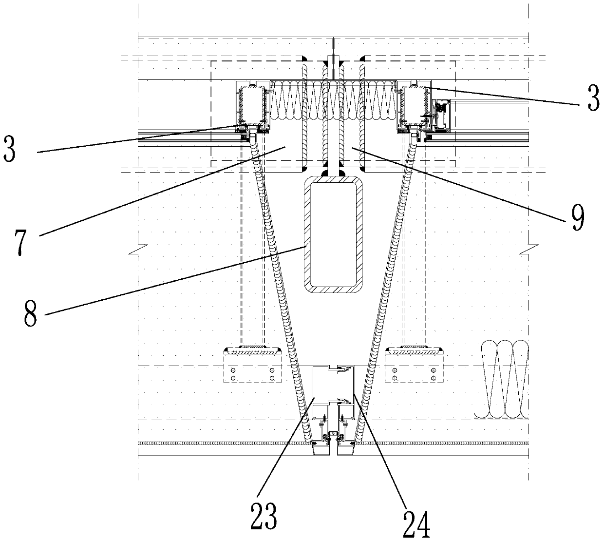
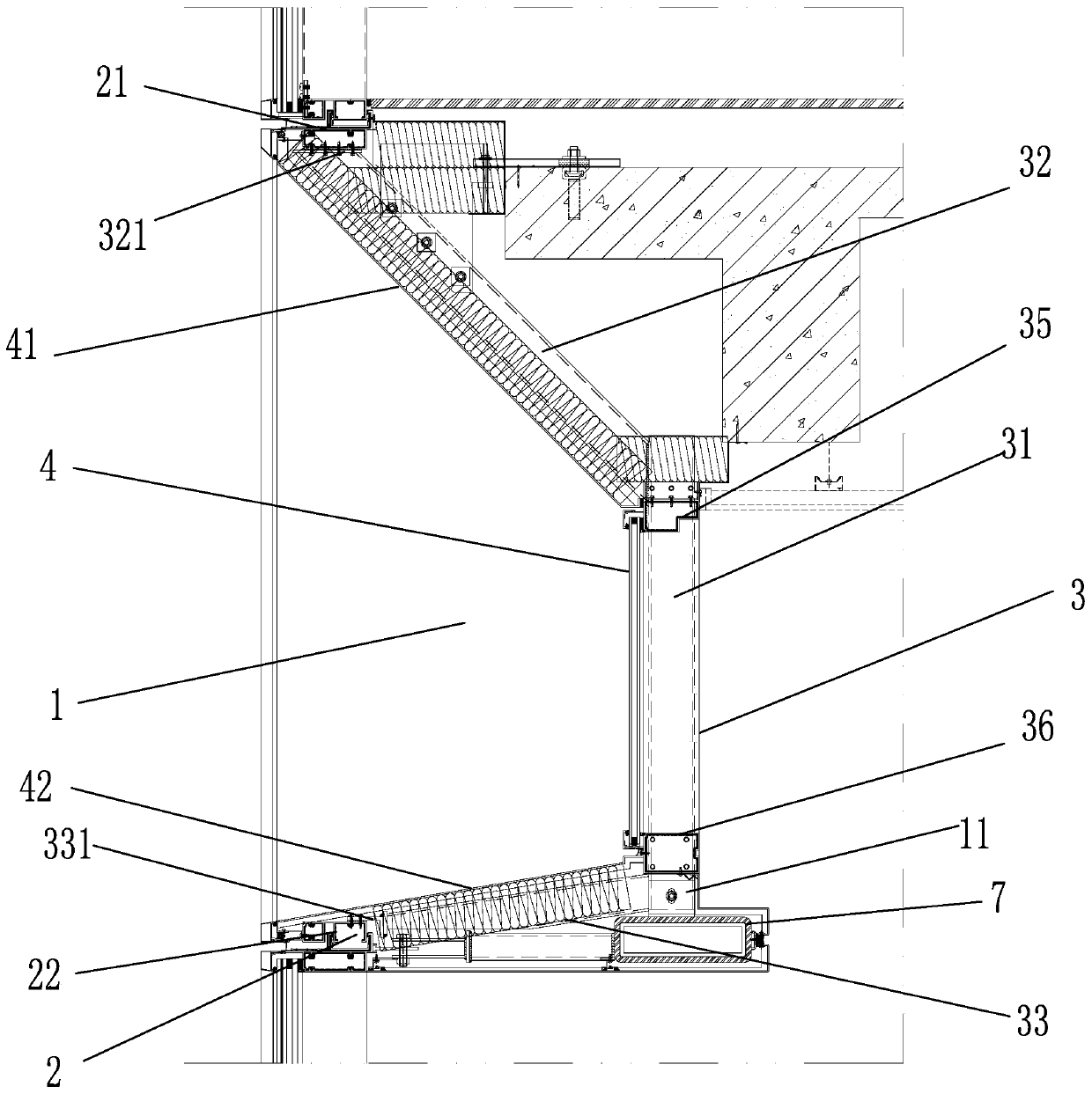
[0026] Such as Figure 1-Figure 7 As shown, the present invention provides an interlayer concave combined unit curtain wall, which includes a plurality of concave units 1, and each concave unit 1 is successively connected in the horizontal direction. The concave unit 1 includes a rectangular frame 2 and several single frames 3 .

[0027] The rectangular frame 2 includes an upper crossbeam 21 and a lower crossbeam 22, both ends of which are fixedly connected by a public upright post 23 and a female upright post 24, respectively. The male uprights 23 and the female uprights 24 of adjacent female units 1 are inserted and fixed to each other.

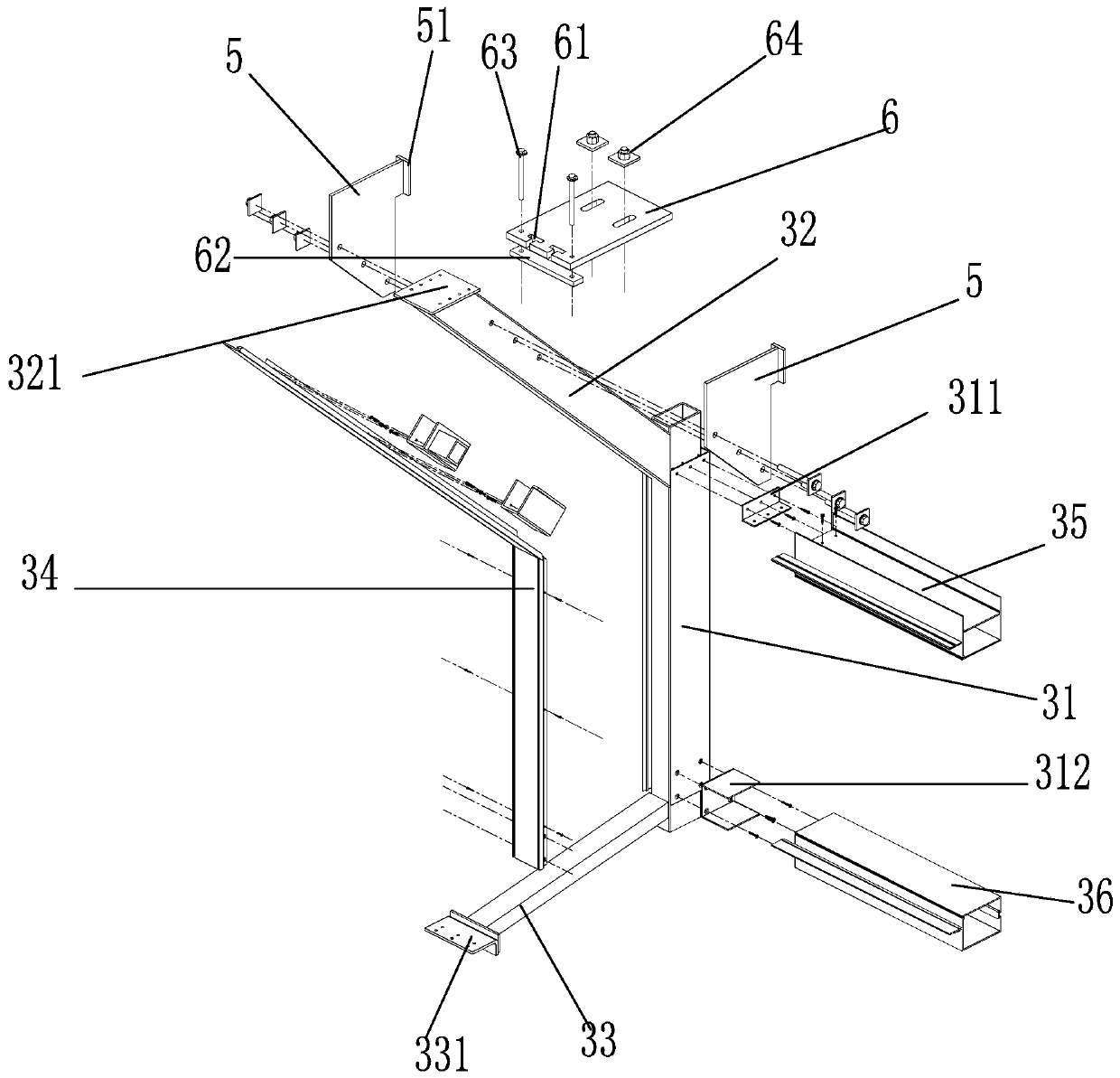
[0028] The single frame 3 includes a vertical single column 31, the top and bottom of the single column 31 are respectively fixed with an upper connecting beam 32 and a lower connecting beam 33, and the out...


PUM


Abstract

An interlayer concave combined type unit curtain wall comprises a plurality of concave units. Each concave unit comprises a rectangular frame and a plurality of single frames. Each rectangular frame comprises an upper cross beam, a lower cross beam, a male upright post and a female upright post. Each single frame comprises a vertical single stand column, and an upper connecting beam and a lower connecting beam are fixedly arranged at the top and the bottom of each single stand column respectively. The tail ends of the upper connecting beams are provided with horizontal upper fixing plates, theupper fixing plates are fixedly connected with the bottom surface of the upper cross beams, the tail ends of the lower connecting beams are provided with L-shaped lower fixing plates, the lower fixing plates are provided with horizontal first plates and vertical second plates, the first plates are fixedly connected with the top surfaces of the lower cross beams, and the second plates are fixedlyconnected with the tail ends of the lower connecting beams. The two sides of the top of each single stand column are fixedly provided with L-shaped upper supporting plates, the two sides of the bottomof each single stand column are fixedly provided with U-shaped lower supporting plates, upper single cross beams are fixed between the upper supporting plates of every two adjacent single stand columns, and lower upper single cross beams are fixed between the lower supporting plates of every two adjacent single stand columns.

Description

technical field [0001] The invention belongs to the technical field of building curtain walls, in particular to an interlayer concave combined unit curtain wall. Background technique [0002] In the prior art, the interlayer special-shaped curtain wall metal plate decorative strip curtain wall is generally designed according to the frame system, there are many vertical decorative metal plate components, the quality of on-site installation cannot be guaranteed, and the installation is complicated, the construction is difficult, the labor cost is high, and the installation period long. In addition, the above-mentioned technology does not have a complete waterproof system, and there are hidden dangers of water leakage. The splicing design of the transfer aluminum column adopts the splicing design of sleeve connection and welding. The process is complicated, and the strength of the aluminum column decreases greatly after welding, and the flatness is difficult to guarantee. Con...

Claims


Application Information

Patent Timeline
Patent Type & Authority Applications(China)
IPC IPC(8): E04B2/88E04B2/96
CPCE04B2/88E04B2/96
Inventor 贺有礼姜晓光韩维池
Owner BEIJING JANGHO CURTAIN WALL SYST ENG
Learn More