Integrated decorative suspended ceiling
A technology for suspended ceilings and ceiling panels, which is applied to ceilings, buildings, and building components. It can solve problems such as unreasonable internal cooperation of ceiling fasteners, inconvenient maintenance and disassembly, and shaking of ceiling panels, so as to achieve diversified ceiling structures, ensure stability, Eliminate the shaking effect
- Summary
- Abstract
- Description
- Claims
- Application Information
AI Technical Summary
Problems solved by technology
Method used
Image
Examples
Embodiment 1
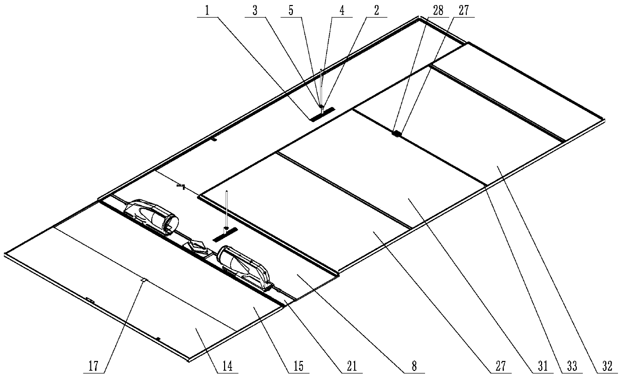
[0083] Such as Figure 1-Figure 13 As shown, the present invention is an integrated decorative ceiling, which includes a ceiling module, a decorative panel offset overlapping module and a decorative panel flat connection module. Ceiling fasteners, the two sides of the ceiling board 8 are respectively connected with the flat connection module of the decorative board and the dislocation overlapping module of the decorative board, and the lower surface of the ceiling board 8 is a decorative surface;
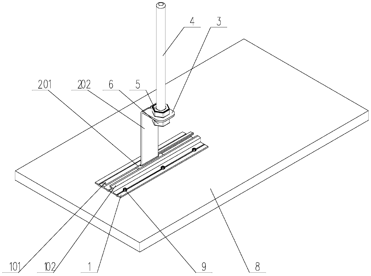
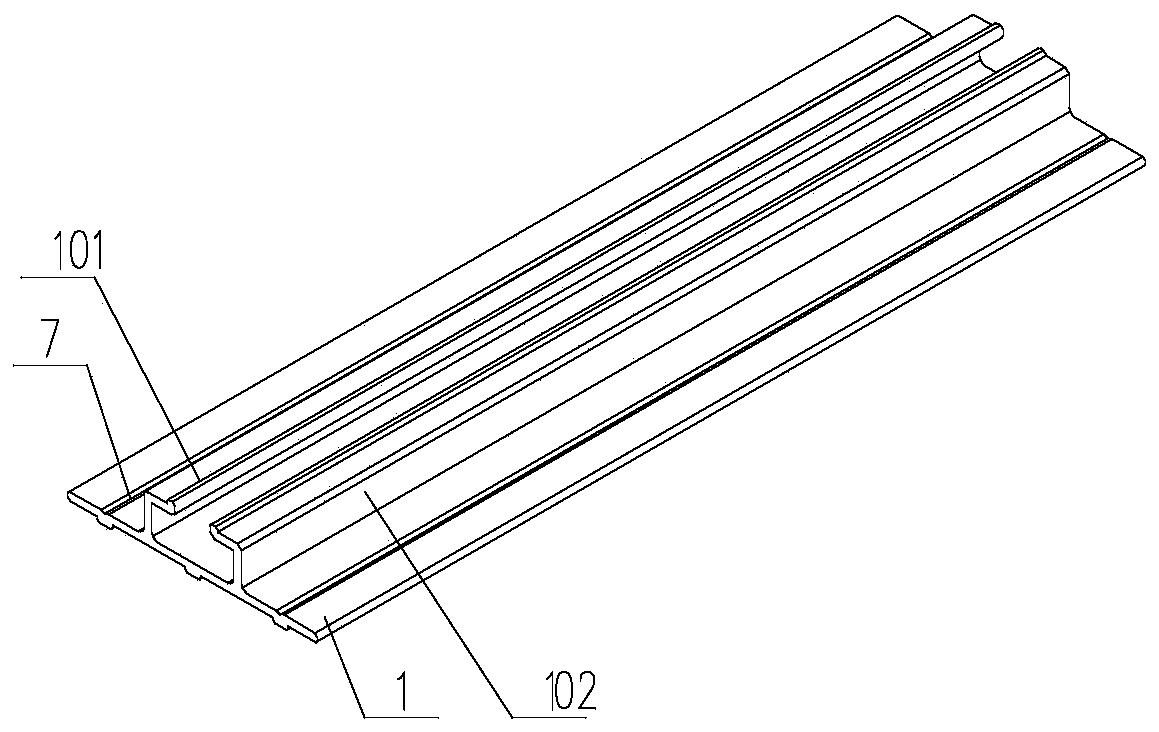
[0084] The ceiling fastener includes a clamping plate 2 and a positioning plate 1 fixed on the upper surface of the ceiling plate 8 by fasteners. The upper surface of the positioning plate 1 protrudes into strips, and there are two strips. They are respectively the left slat 101 and the right slat 102, the surfaces of the left slat 101 and the right slat 102 facing each other and the position on the positioning plate 1 between the left slat 101 and the right slat 102 form an opening...
Embodiment 2
[0093] This embodiment is based on the first embodiment, and makes the first implementation description for the structure of the installation through groove 103 .
[0094] In the present invention, preferably the installation through groove 103 is a T-shaped groove, specifically, as Figure 1-12 As shown, the cross section of the slats is L-shaped, and the left slat 101 and the right slat 102 are symmetrically arranged on the positioning plate 1, the vertical plate A of the left slat 101 and the vertical plate A of the right slat 102 The straight boards A are all connected to the positioning board 1 as a whole, and the end of the horizontal board A of the left batten 101 and the end of the horizontal board A of the right batten 102 are opposite to each other.
[0095] At this time, there are three specific interference fit methods between the clamping plate 2 and the installation through groove 103 as follows:
[0096] method one,
[0097] In this manner, the other end of th...
Embodiment 3
[0112] This embodiment is based on the first embodiment, and makes a second implementation description for the structure of the installation channel 103 .
[0113] The left slat 101, the right slat 102 and the positioning plate 1 can form a dovetail groove. When it is a dovetail groove, since the groove wall is a slope, in order to improve the interference fit between the positioning plate 1 and the clamping plate 2 The contact surface on the size part is as large as possible, and it is preferable to process a plane consistent with the slope of the inclined surface on the part of the clamping plate 2 that needs to be in contact with the inclined surface, so that the positioning plate 1 and the clamping plate 2 are in an interference fit. , there is surface-to-surface contact between them.
[0114] The specific cooperation modes of the positioning plate 1 and the clamping plate 2 can be adjusted correspondingly with reference to the three modes in Embodiment 2.
PUM
 Abstract
Description
Claims
Application Information
 - R&D
- Intellectual Property
- Life Sciences
- Materials
- Tech Scout
- Unparalleled Data Quality
- Higher Quality Content
- 60% Fewer Hallucinations
Browse by: Latest US Patents, China's latest patents, Technical Efficacy Thesaurus, Application Domain, Technology Topic, Popular Technical Reports.
© 2025 PatSnap. All rights reserved.Legal|Privacy policy|Modern Slavery Act Transparency Statement|Sitemap|About US| Contact US: help@patsnap.com


