Eureka AIR delivers breakthrough ideas for toughest innovation challenges, trusted by R&D personnel around the world.

Downhole flow control valve

A technology of flow control valve and choke valve sleeve, which is used in wellbore/well valve devices, wellbore/well components, sealing/packing, etc. problems, to achieve the effect of reducing processing costs, simple and practical movement principle, and convenient operation

Active Publication Date: 2021-11-16
CHINA NAT OFFSHORE OIL CORP +1
View PDF20 Cites 0 Cited by
  • Summary
  • Abstract
  • Description
  • Claims
  • Application Information

AI Technical Summary

Problems solved by technology

Using intelligent completion technology, the flow rate of downhole production layers can be controlled. If you only need to open or close the production layer, you can use two downhole flow control valves to achieve it; if you want to control the flow rate of a single production layer more accurately, A flow control valve with two openings is obviously impossible to realize
Patent CN201410618870.5 uses J-shaped grooves to achieve different openings of fracturing sleeves through rotation. If hydraulic control is used, repeated positive and negative pressure is required to realize multi-stage switch fracturing of downhole fracturing sleeves; CN201720642612.X adopts Electronic control to realize the opening and closing of the sliding sleeve requires the participation of electrical components. In the underground high temperature and high pressure environment, the durability is not easy to meet

Method used


Image

  • Downhole flow control valve
  • Downhole flow control valve
  • Downhole flow control valve

Examples


Embodiment Construction

[0032] Preferred embodiments of the present invention will be described in detail below with reference to the accompanying drawings, so as to better understand the purpose, features and advantages of the present invention. It should be understood that the embodiments shown in the drawings are not intended to limit the scope of the present invention, but only to illustrate the essence of the technical solutions of the present invention.

[0033] In the description of the present invention, it should be understood that the orientations or positional relationships indicated by the terms "upper", "lower", "inner", "outer", "front", "rear" etc. are based on the orientations shown in the drawings Or positional relationship is only for the convenience of describing the present invention and simplifying the description, but does not indicate or imply that the device or element referred to must have a specific orientation, be constructed and operated in a specific orientation, and there...


PUM


Abstract

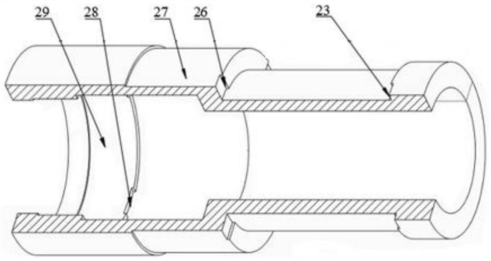
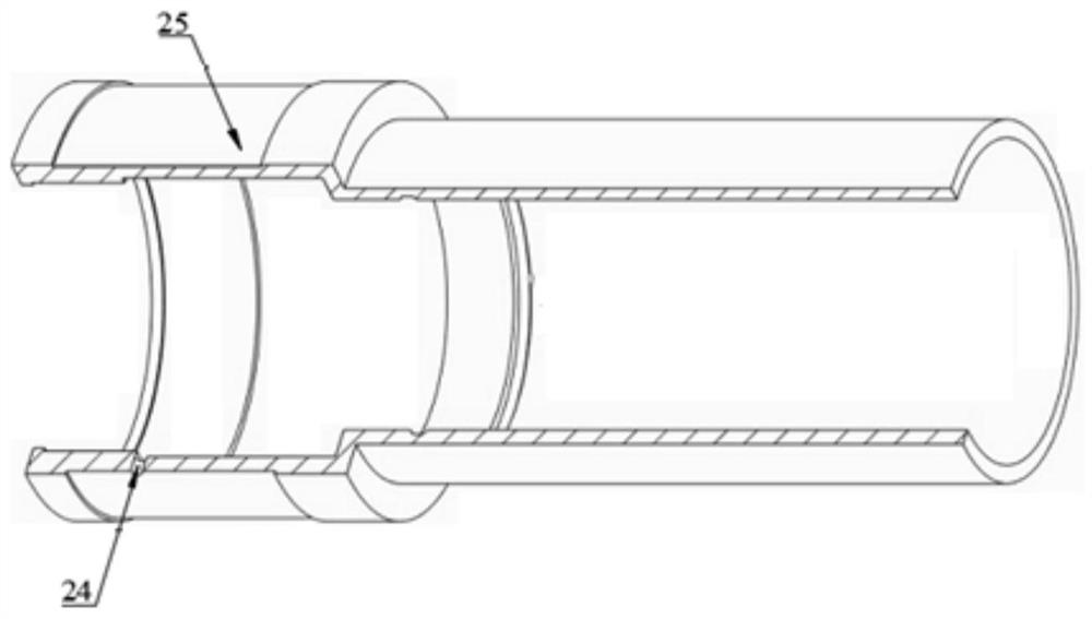
The invention discloses an underground flow control valve, which comprises an upper valve body, a first-stage liquid cylinder inner cylinder, a first-stage piston, a second-stage piston, a lower valve body and a throttle valve sleeve; the first-stage liquid cylinder inner cylinder It is arranged inside the upper valve body; the first-stage piston is arranged in the upper valve body, and the first step end surface of the inner cylinder of the first-stage hydraulic cylinder and its outer peripheral wall, the upper valve body and the first-stage piston are surrounded by the first oil Cavity, the outer peripheral wall of the inner cylinder of the first-stage hydraulic cylinder and its second step end face, the inner peripheral wall of the first-stage piston and its first step end face form a second oil chamber, and the second-stage piston is arranged in the upper valve body , the second step end face of the first stage piston and its outer peripheral wall, the upper valve body and the second stage piston form a third oil chamber, the third step end face of the first stage piston and its outer peripheral wall, the second stage piston The fourth oil chamber is enclosed between the first step end surface of the first step and its inner peripheral wall; the lower valve body is connected to the other end of the upper valve body, and the throttle valve sleeve is fixedly arranged in the lower valve body.

Description

technical field [0001] The invention relates to a downhole flow control valve, in particular to a downhole flow control valve device applied to a multi-opening intelligent well completion system in oil drilling and completion and oil and gas exploitation. Background technique [0002] The intelligent completion technology mainly realizes the remote control of the downhole flow control valve through hydraulic power, and can complete the control of the production flow rate of the downhole oil and gas layers on the ground, and realize the arbitrary switching of multi-production modes such as multi-layer co-production and inter-layer optimization. . Using intelligent completion technology, the flow rate of downhole production layers can be controlled. If you only need to open or close the production layer, you can use two downhole flow control valves to achieve it; if you want to control the flow rate of a single production layer more accurately, The flow control valve of two o...

Claims


Application Information

Patent Timeline
Patent Type & Authority Patents(China)
IPC IPC(8): E21B34/06E21B34/14
CPCE21B34/06E21B34/14
Inventor 许亮斌何玉发何东升刘书杰刘清友杨仪伟盛磊祥郑严肖凯文仝迪
Owner CHINA NAT OFFSHORE OIL CORP
Why Eureka
Eureka Blog
Learn More