
Adjustable stable tunnel supporting structure with high fit degree

An adjustable support structure technology, applied in tunnels, tunnel linings, shaft linings, etc., can solve problems such as poor flexibility, adjustment, and affecting the stability of construction positions, and achieve high matching, enhanced stability, and flexible adjustment processes Effect

Pending Publication Date: 2020-04-21
ZHEJIANG UNIV OF TECH
View PDF0 Cites 3 Cited by
  • Summary
  • Abstract
  • Description
  • Claims
  • Application Information

AI Technical Summary

Problems solved by technology

At present, the most frequently used tunnel support structure is anchor cable support. The support surface connected with the top of the tunnel is often an integral arch body, which has poor flexibility, and due to the rock structure and soil layer in the tunnel Under the influence of various factors of the external environment, the structure will shrink or expand, and it cannot be adjusted according to different situations, which will lead to a low degree of fit with the junction of the tunnel roof, and it will not be able to fully support the construction position, which will affect the construction. The stability of the positional support, so there is an urgent need for an adjustable and stable tunnel support structure with a high degree of fit to solve the above problems

Method used


Image

  • Adjustable stable tunnel supporting structure with high fit degree
  • Adjustable stable tunnel supporting structure with high fit degree
  • Adjustable stable tunnel supporting structure with high fit degree

Examples


Embodiment Construction

[0025] The following will clearly and completely describe the technical solutions in the embodiments of the present invention with reference to the accompanying drawings in the embodiments of the present invention. Obviously, the described embodiments are only some, not all, embodiments of the present invention. Based on the embodiments of the present invention, all other embodiments obtained by persons of ordinary skill in the art without creative efforts fall within the protection scope of the present invention.

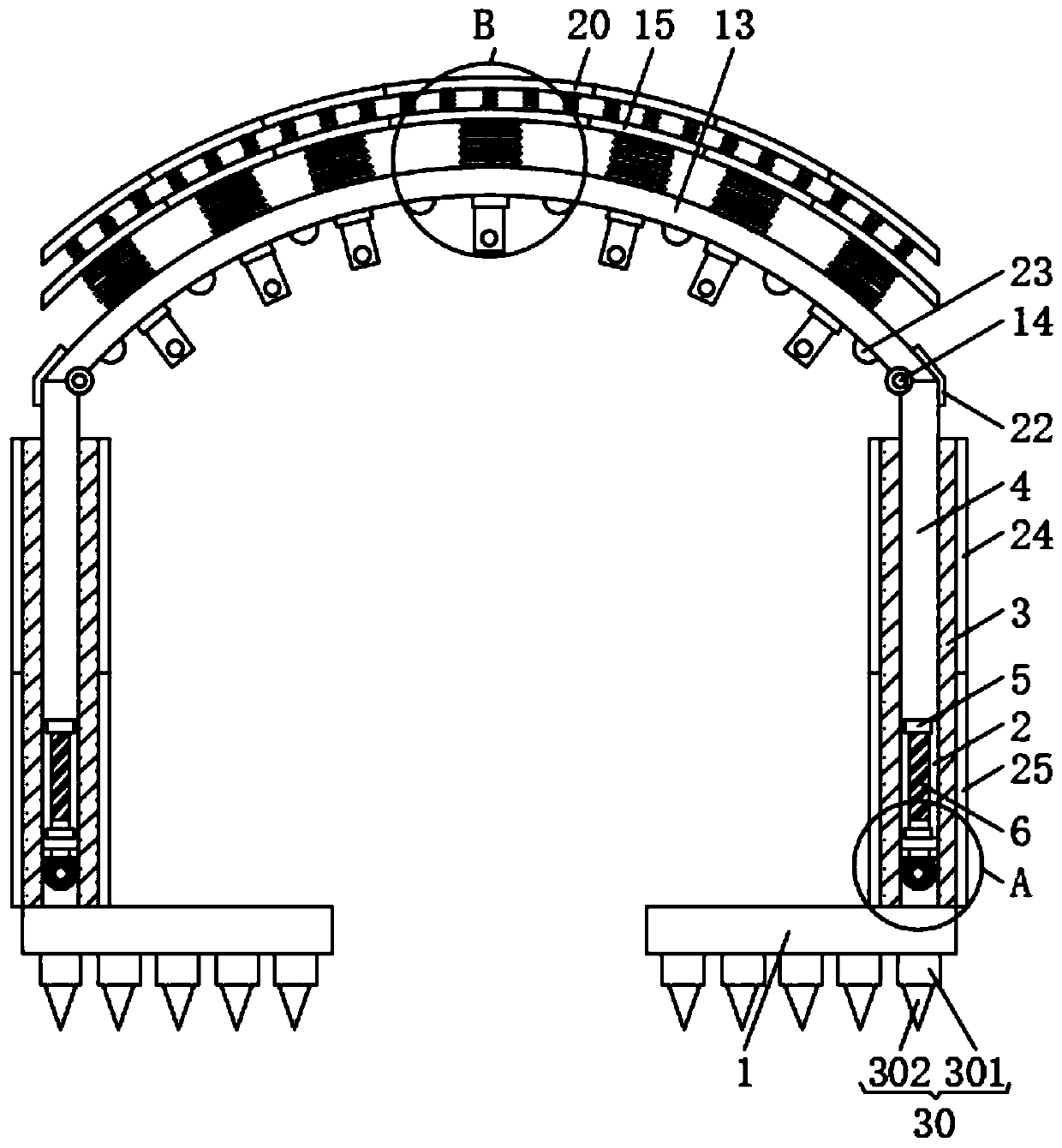
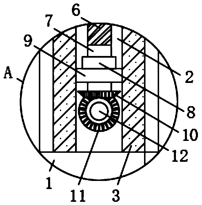
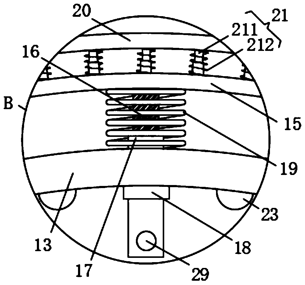
[0026] see Figure 1-7 , the present invention provides a technical solution: an adjustable and stable tunnel support structure with a high degree of matching, including pillars arranged on the side walls of the tunnel, and rigid support arches supporting the top of the tunnel are erected on the pillars on both sides frame 13, the pillars are supported on the base 1, and the base 1 is a flat and long box surrounded by two prisms 2 arranged axially forward and backw...


PUM


Abstract

The invention provides an adjustable stable tunnel supporting structure with high fit degree. A rigid supporting arch frame for supporting the top of a tunnel is erected on a supporting column, wherein a lifting seat is arranged in a cavity of a flat and long box body of the supporting column; the bottom of the lifting seat is connected with a first threaded cylinder; the first threaded cylinder is meshed with a first threaded column; the bottom end of the first threaded column is connected with a first rotating shaft, the first rotating shaft is arranged on a bearing seat in a penetrating mode through a first bearing; a driven bevel gear is arranged at the lower end of the first rotating shaft; a driving bevel gear is connected with a second rotating shaft; a second bearing is arranged ona prism; a rigid adjustable top plate is erected on the rigid supporting arch frame, and a flexible adjustable top plate is erected on the rigid adjustable top plate through an elastic device; and the bottom of the rigid adjustable top plate is connected with a second threaded cylinder through a second threaded column, the second threaded cylinder is arranged on the rigid supporting arch frame ina penetrating mode through a third bearing, the second threaded column is sleeved with a supporting spring, and the lower end of the second threaded cylinder is connected with a rocker through a second driving connecting hole.

Description

technical field [0001] The invention relates to a tunnel support structure. Background technique [0002] A tunnel is a building built underground or underwater or in a mountain, laying a railway or building a road for the passage of motor vehicles. According to its location, it can be divided into three categories: mountain tunnels, underwater tunnels and urban tunnels. In order to shorten the distance and avoid large ramps, it is called a mountain tunnel that passes under mountains or hills; in order to cross rivers or straits, it is called an underwater tunnel that passes under a river or under the sea; in order to meet the needs of railways passing through large cities, it is called a tunnel. Those that pass underground are called urban tunnels. Among these three types of tunnels, mountain tunnels are the most constructed. [0003] The foundation pit support is to ensure the safety of the underground structure construction and the surrounding environment of the founda...

Claims


Application Information

Patent Timeline
IPC IPC(8): E21D11/18
CPCE21D11/18E21D11/183
Inventor 王克忠刘华
Owner ZHEJIANG UNIV OF TECH
Learn More