Testing method and loading device for reinforced concrete bond-slip performance based on corrosion and fatigue load coupling influence

A reinforced concrete, bond-slip technology, applied in the direction of measuring devices, mechanical devices, instruments, etc., can solve problems such as low efficiency, easy slurry leakage, uncontrollable loading rate, etc., and achieve the effect of convenient operation and high measurement accuracy

Inactive Publication Date: 2017-10-10
ZHEJIANG UNIV
View PDF9 Cites 16 Cited by
  • Summary
  • Abstract
  • Description
  • Claims
  • Application Information

AI Technical Summary

Problems solved by technology

[0007] The Chinese invention patent with the application number 201210162916.8 discloses a cylindrical specimen for measuring the bonding force between steel bars and concrete, which passes the steel bar through a cylindrical PVC pipe and passes through a circle whose diameter is equal to the outer diameter of the cylindrical PVC pipe. The disadvantages of this technical solution are: ① Fix the PVC pipe and the steel plate by tape, which is easy to leak when vibrating the concrete, and the efficiency is low, so it is not suitable for large-scale comparative tests; ② The thickness of the protective layer of the cylindrical test block is much larger than that of the actual structure, and the stirrups cannot be placed. When the test block is loaded, the concrete is compressed and the steel bars are easily pulled, making it impossible to truly simulate the bond in the reinforced concrete beam. State of stress
[0008] The Chinese invention patent with the application number 201510688835.5 discloses a pull-out device for measuring the bonding performance of steel bars and concrete. Force loading, the disadvantage of this technical solution is that the protective la

Method used


Image

  • Testing method and loading device for reinforced concrete bond-slip performance based on corrosion and fatigue load coupling influence
  • Testing method and loading device for reinforced concrete bond-slip performance based on corrosion and fatigue load coupling influence
  • Testing method and loading device for reinforced concrete bond-slip performance based on corrosion and fatigue load coupling influence

Examples


Example Embodiment

[0044] The method for studying the bond-slip performance of ordinary deformed steel bars, corroded deformed steel bars and concrete based on beam end components of the present invention will be described in detail below in conjunction with the accompanying drawings.

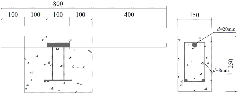
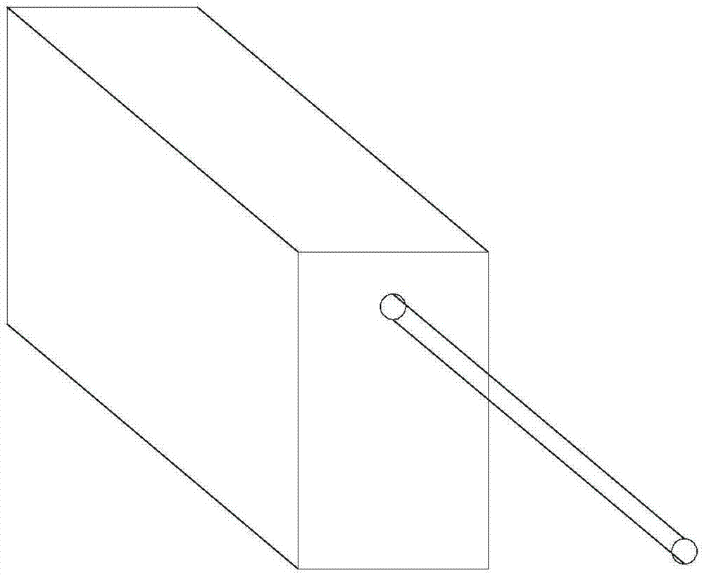
[0045] like figure 1 As shown, step 1: test block pouring

[0046] Make a wooden mold whose length, width and height are 300×150×250 mm, and punch holes at both ends of the wooden mold along the length direction. There are two round holes with a hole diameter of 25mm on the bottom side of the wooden formwork. The distance from the center of the hole to the bottom is determined by the thickness of the protective layer, and the distance to both sides is 75mm; there are four round holes with a hole diameter of 8mm on the top of the wooden formwork. The distances from the center to the sides and top are 30mm and 50mm, respectively. Place stirrups in the wooden formwork, and insert 20mm hot-rolled deformed steel bar...


PUM

PropertyMeasurementUnit
Corrosion current densityaaaaaaaaaa

Abstract

The invention provides a testing method and loading device for reinforced concrete bond-slip performance based on corrosion and fatigue load coupling influence. The device comprises an external reaction frame and is characterized in that an MTS testing machine is arranged on the external reaction frame, and a conversion connector and an anchor are mounted at the end of the MTS testing machine; an internal reaction frame is arranged right below the MTS testing machine and provided with a station for placing a to-be-tested block, and the station is a square space jointly formed by a first retaining plate, a second retaining plate, a first fastening screw and a second fastening screw in an enclosed manner; a first clamp is mounted at the top end of the first retaining plate, and a first displacement sensor is fixed on the first clamp; a second clamp is mounted at the bottom end of the second retaining plate, and a second displacement sensor is fixed on the second clamp. The testing method and loading device has the advantages that parameters such as reinforced concrete bond-slip performance under corrosion and fatigue load coupling influence can be measured objectively and accurately, and the method is simple and convenient in testing.

Description

technical field [0001] The invention relates to the technical field of civil engineering concrete structure tests, in particular to a test method and a loading device for the bond-slip performance of reinforced concrete based on the coupling effect of corrosion and fatigue loads. Background technique [0002] The stress transfer and deformation coordination between steel bars and concrete in reinforced concrete structures are realized through the bonding between the two. The chemical adhesive force, friction force and mechanical bite force between steel bars and concrete constitute the bonding force of reinforced concrete structures. knot force. Adequate bonding between steel bars and concrete is the premise and foundation for reinforced concrete structures to exert good working performance. The relationship between the local bond stress of steel bars and the local relative slip is called the bond-slip constitutive relationship, which reflects the contact behavior of steel ...

Claims


Application Information

Patent Timeline
IPC IPC(8): G01N19/04
CPCG01N19/04
Inventor 林红威赵羽习刘承斌
Owner ZHEJIANG UNIV
Why Eureka
Try Eureka