A generator installation

A technology for installation devices and generators, applied in the field of high-voltage power transmission and distribution, can solve problems such as unreliability, thermal stability changes, and inability to install intelligent electronic equipment, and achieve the effect of not easy to fall off and stable fall off

Active Publication Date: 2021-03-16
STATE GRID CORP OF CHINA +2
View PDF17 Cites 0 Cited by
  • Summary
  • Abstract
  • Description
  • Claims
  • Application Information

AI Technical Summary

Problems solved by technology

Such as: overhead transmission lines, cables, ring network cabinets, monitoring, monitoring, warning and other equipment on high-voltage transmission lines, and various expansion applications (such as field communication base stations), etc. Many intelligent electronic equipment cannot be installed due to lack of power. The traditional power supply methods of these devices mostly use expensive and bulky solar or wind energy and CT (inductive power acquisition) power generation equipment
[0003] There are more or less problems in traditional power supply methods: 1. Solar power generation equipment cannot achieve what it wants due to sunlight, night and weather.
2. Wind power generation equipment is affected by construction cost, geographical location, weather and climate
3. The use of CT (inductive power harvesting) changes the distribution of the electric field, causing heating of the internal insulation and changes in thermal stability, which seriously threatens the normal operation of the power system. Therefore, the way of CT power harvesting is an unreliable way

Method used


Image

  • A generator installation
  • A generator installation
  • A generator installation

Examples


Embodiment 1

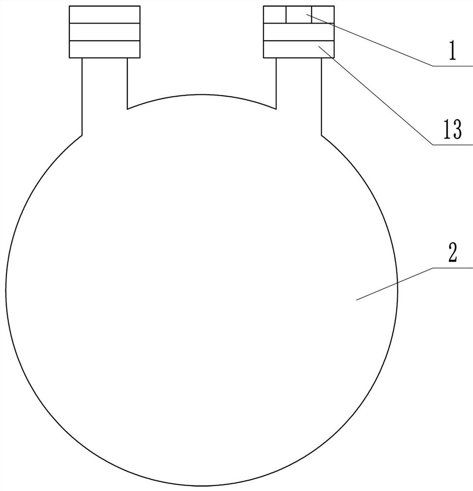
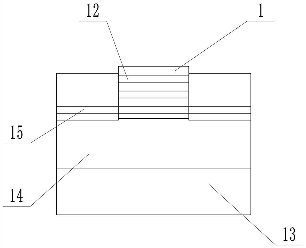
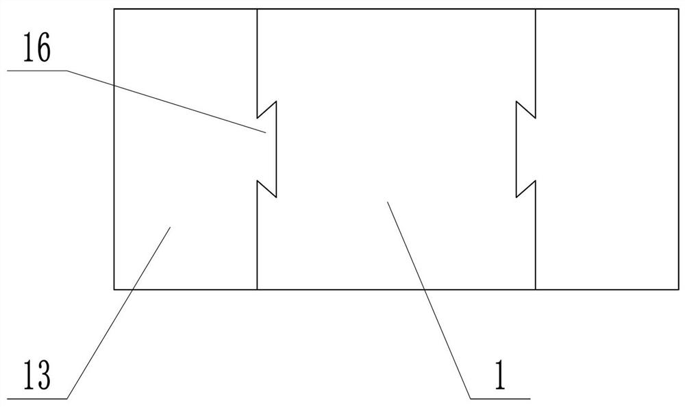
[0038] as attached Figure 1-3 As shown, the present invention includes a base 13, a wire passing hole 14 provided on the base 13, and a pressing plate 1 arranged on the base 13 through a mortise and tenon structure. 1, there is a dovetail projection 16 on the side wall of the installation groove, and the dovetail groove corresponding to the dovetail projection 16 is arranged on the pressing plate 1, and the dovetail projection 16 is vertically arranged. When the pressing plate 1 After mating with the base 13, the pressing plate 1 can only move up and down in the vertical direction.

[0039] The front side wall of the base 13 is provided with a base draw-in slot 15, and several press-plate draw-in slots 12 are correspondingly arranged on the front side wall of the press plate 1, between the base draw-in slot 15 and the corresponding press plate draw-in slot 12 Set with cardboard. The inner diameter of the wire hole 14 should be large enough. Adjust the position height of the...

Embodiment 2

[0042] as attached Figure 4 , 5 As shown, the generator of this embodiment includes a casing 2 fixed on the base 13, a winding 3 installed in the casing 2, a corona generator set in the casing 2, and a corona generator set inside the corona generator. Rotor and Stator 9.

[0043] The corona generator includes a sleeve 17 arranged in the housing 2, an installation base 6 arranged on the outer side wall of the sleeve 17, a spiral sleeve 5 fixed on the installation base 6, and a metal sleeve installed on the outer end of the spiral sleeve 5. The ball 4 is provided with a through hole 10 on the mounting base 6 , and a hole corresponding to the through hole 10 is provided on the sleeve 17 .

[0044] There are 12 mounting bases 6 and they are evenly arranged on the outer wall of the sleeve 17 , and a spiral sleeve 5 is fixed on each mounting base 6 .

[0045] The housing 2 is cylindrical, and there are glass bells at both ends of the cylinder of the housing 2. In order to reduce...

Embodiment 3

[0052] In this embodiment, on the basis of Embodiment 1 and Embodiment 2, the casing 2 is improved.

[0053] as attached Figure 7 As shown, the housing 2 of this embodiment includes an upper housing 201 and a lower housing 202 that are engaged with each other. The upper and lower housings are semicircular. It is in sealing contact with the fastened upper and lower shells to ensure the sealing performance.

[0054] The casing 2, the base 13 and the pressure plate 1 of the present invention are all made of insulating materials, which can better protect the field strength. According to the corona law: the corona phenomenon is most likely to appear at the opening of the electric field rod hanging slot and the winding out of the slot The mouth is a typical casing structure. The corona generator used in the present invention is a metal wire spiral casing structure. The metal wire in the groove is in poor contact and there is an air gap. Because the electric field of the spiral gro...


PUM


Abstract

The invention relates to a generator installation device, which comprises a base, a wire passing hole formed in the base and a pressing plate arranged on the base through a mortise and tenon joint structure, wherein the base is provided with an installation groove used for being matched with the pressing plate, a dovetail-shaped protruding block is arranged in the installation groove, and a dovetail groove matched with the dovetail-shaped protruding block is formed in the pressing plate; and a generator is fixed below the base. According to the invention, a wire in the wire passing hole is pressed by adopting the base and the pressing plate which are connected through the mortise and tenon joint structure, the positions between pressing plate clamping grooves and corresponding base clamping grooves can be adjusted, the fixation is carried out through clamping plates, the connection work of the wires with different outer diameters can be achieved, and the generator is stable and not prone to falling off after being installed.

Description

technical field [0001] The invention relates to the technical field of high-voltage power transmission and distribution, in particular to a generator installation device. Background technique [0002] With the growth of national power demand and the improvement of line design requirements, the modern power transmission system is gradually developing rapidly in the direction of high voltage, large span, and large capacity. The large span and long-distance power transmission of EHV and With the construction of smart grid, the development of society has driven the increase in demand for electric energy, and the pace of power system construction has been accelerated in the promotion of the construction of world-class energy Internet enterprises of "three types and two networks", "strong grid" and "smart grid". The increase in the use of advanced equipment for power transmission and distribution transformation equipment, and the demand for the installation of intelligent electron...

Claims


Application Information

Patent Timeline
Patent Type & Authority Patents(China)
IPC IPC(8): F03D13/20F03D9/25F03D9/43H02G7/00
CPCF03D9/25F03D9/43F03D13/20H02G7/00Y02B10/30Y02E10/72Y02E10/728
Inventor 何成立陈岩申金龙赵庆华谷红彬张炜李洪宾段泽龙宋计林曹轩田晨华何菲赵立城
Owner STATE GRID CORP OF CHINA
Why Eureka
Try Eureka