Waveguide frequency converter mounting box and waveguide frequency converter line cementing tool

A frequency converter and installation box technology, which is applied in the direction of support structure installation, material gluing, circuit arrangement on the support structure, etc. It can solve the problem of loose terminals, affecting the use of external equipment, and difficulty in adapting to the installation of KA frequency band transceivers, etc. problems, to achieve the effect of preventing loosening and detachment

Active Publication Date: 2020-04-21
常州市瑞昱通信设备制造有限公司
View PDF6 Cites 2 Cited by
  • Summary
  • Abstract
  • Description
  • Claims
  • Application Information

AI Technical Summary

Problems solved by technology

The waveguide inverter is usually installed in the box body 04 when in use, and is used for installation with external equipment. The existing installation box for the waveguide inverter is difficult to adapt to the installation of the KA frequency band transceiver. Therefore, there is an urgent need for a Waveguide inverter installation box, used to install the KA band transceiver
In addition, the wires in the installation box of the existing waveguide inverter are loose and not fixed. When the installation box and external equipment vibrate violently during use, it is easy to cause the wiring terminal between the wire and the inverter body to become loose or even detached. , affecting the use of exogenous equipment

Method used


Image

  • Waveguide frequency converter mounting box and waveguide frequency converter line cementing tool
  • Waveguide frequency converter mounting box and waveguide frequency converter line cementing tool
  • Waveguide frequency converter mounting box and waveguide frequency converter line cementing tool

Examples


Embodiment Construction

[0034] The present invention will be described in further detail below in conjunction with the accompanying drawings.

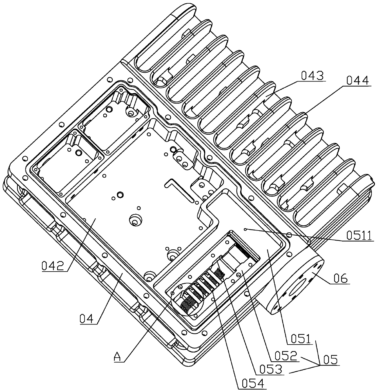
[0035] refer to figure 2 , is a waveguide inverter installation box disclosed in the present invention, including a box body 04, the box body 04 is in the shape of a rectangular block, the upper surface of the box body 04 is provided with an installation groove 05 and a receiving groove 042, and there are multiple receiving grooves 042, Used to install other components on the external device. The upper surface of the box body 04 is also provided with a heat dissipation groove 043. The opening of the heat dissipation groove 043 is rectangular. , and the heat dissipation groove 043 communicates with the outer side wall of the box body 04 away from the receiving groove 042 to form a heat dissipation fin 044 integrally formed with the box body 04 to accelerate the heat emitted by the components on the box body 04 during operation.

[0036] refer to figure 2 ...


PUM


Abstract

The invention relates to a waveguide frequency converter mounting box. The mounting box comprises a box body, wherein a mounting groove used for containing and installing a frequency converter body isformed on the box body, the mounting groove is a stepped groove, a plurality of long grooves arranged in the length direction of the mounting groove are formed on an inner bottom face of the mountinggroove, inner side walls, close to each other, of the long grooves are provided with communicating grooves for wires to pass through, a supporting bridge for supporting the frequency converter body is formed between the long grooves, a bottom surface of the box body is provided with a wire outlet groove communicated with the long groove closest to a side wall of the box body, the box body is integrally provided with a plugging groove body used for plugging an antenna, and an inner bottom surface of the mounting groove is provided with a wire through hole communicated with the plugging groovebody. The mounting box has the effect of adaptively mounting a KA frequency band transceiver.

Description

technical field [0001] The invention relates to the technical field of mechanical processing, in particular to a waveguide frequency converter installation box and a waveguide frequency converter circuit glue fixing tool. Background technique [0002] The KA frequency band is the main working frequency band of satellite communication. It has the advantages of frequency bandwidth, large information capacity, small equipment size, anti-interference performance and concealment, and can meet the requirements of high-speed, broadband and small-caliber terminal applications. Therefore, the KA frequency band satellite communication It is an important trend in the development of satellite communications. The waveguide frequency converter is an important waveguide component often involved in the modern communication technology industry. There is a KA frequency band transceiver such as figure 1 As shown, its structure includes the inverter body 01, antenna 03 and multiple wires 02 co...

Claims


Application Information

Patent Timeline
Patent Type & Authority Applications(China)
IPC IPC(8): F16B11/00H04B1/40H05K7/02H05K7/14
CPCF16B11/006H04B1/40H05K7/02H05K7/1447
Inventor 张建兴杨梓张寅
Owner 常州市瑞昱通信设备制造有限公司
Why Eureka
Try Eureka