A crankshaft for a compressor

A compressor and crankshaft technology, applied in the crankshaft field, can solve the problems of destroying the integrity of the crankshaft, easily generating torsional stress, and reducing the structural strength of the crankshaft.

Active Publication Date: 2021-06-15
黄石正达工贸有限公司
View PDF11 Cites 0 Cited by
  • Summary
  • Abstract
  • Description
  • Claims
  • Application Information

AI Technical Summary

Problems solved by technology

[0004] The crankshaft for compressors disclosed in the above-mentioned patents has the following disadvantages: 1. The crankshaft for compressors disclosed in the above-mentioned patents is a rod with a circular cross section. When the crankshaft runs at high speed, it is easy to generate torsional stress. The torsional stress on the cylindrical cross section increases linearly from the center to the outer surface along the axis of the circular section. The crankshaft is easy to bend, twist, deform or break under the action of torsional stress; 2. The above-mentioned patents In order to achieve even distribution of lubricating oil and enhance the effect of crankshaft lubrication in the crankshaft for compressors published in , rectangular oil grooves are arranged on the surface of the short axis, eccentric part and long axis of the crankshaft, which destroys the integrity of the crankshaft and reduces the structure of the crankshaft. strength, the crankshaft is easy to break; therefore, we propose a crankshaft for compressor

Method used


Image

  • A crankshaft for a compressor
  • A crankshaft for a compressor

Examples


Embodiment Construction

[0020] In order to make the purpose, technical solution and advantages of the present invention clearer, the present invention will be further described in detail below in conjunction with the accompanying drawings. Apparently, the described embodiments are only some of the embodiments of the present invention, rather than all of them. Based on the embodiments of the present invention, all other embodiments obtained by persons of ordinary skill in the art without making creative efforts belong to the protection scope of the present invention.

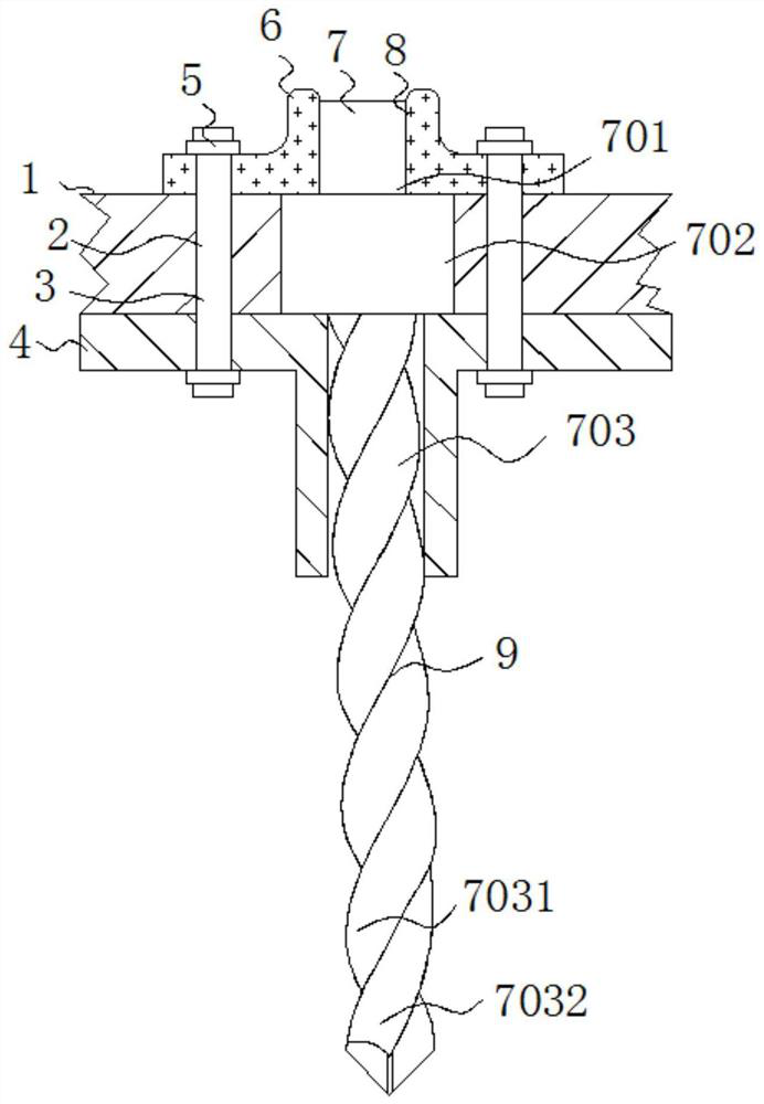
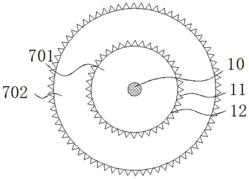
[0021] The following will combine Figure 1 ~ Figure 2 A crankshaft for a compressor according to an embodiment of the present invention will be described in detail.

[0022] refer to figure 1 and figure 2 As shown, a crankshaft for a compressor provided by an embodiment of the present invention includes a crankshaft 7, and the crankshaft 7 includes a short shaft 701, an eccentric portion 702, and a long shaft 703, and the top of the...


PUM


Abstract

The invention discloses a crankshaft for a compressor, which belongs to the technical field of crankshafts and comprises a crankshaft. The crankshaft includes a short shaft, an eccentric part and a long shaft. The top of the eccentric part is fixedly connected with a short shaft, and the bottom of the eccentric part is fixedly connected. There is a long axis, and the long axis is hinged by twisted strip A and twisted strip B. The twist-shaped long shaft has a high structural strength and can withstand large torsional stress. It is not easy to generate torsional stress on the long-term high-speed rotating surface It is bent, twisted or broken to prevent the long axis from being bent, twisted or broken due to long-term high-speed rotation. The short axis and the outer wall of the eccentric part are fixedly connected with triangular saw teeth, and an inverted triangle oil groove B is formed between the triangular saw teeth. An integrated oil groove is formed on the surface of the shaft, and the triangular structure has a high strength to prevent the crankshaft from breaking due to the oil groove on the surface of the crankshaft affecting the structural strength of the crankshaft. A steel wire runs through the inside of the crankshaft to further increase the structural strength of the crankshaft.

Description

technical field [0001] The invention relates to the technical field of crankshafts, in particular to a crankshaft for a compressor. Background technique [0002] The crankshaft of the rotary compressor runs at high speed under the support of the upper flange and the lower flange, so that the compressor compresses the gas to do work. Although there is a certain amount of refrigerated oil between the crankshaft, the upper flange and the lower flange for lubrication, there is also a balance weight to balance it. The inertia of the rotor assembly, etc., but due to the large inertia of the rotor assembly, the balance weight cannot achieve ideal balance, the crankshaft and the flange are tightly attached, and the lubrication is not ideal. The conventional lubrication of the crankshaft and the upper flange is mainly through the upper method. The spiral oil groove of the flange is lubricated, and the distribution of lubricating oil is evenly distributed, without distinguishing the m...

Claims


Application Information

Patent Timeline
Patent Type & Authority Patents(China)
IPC IPC(8): F16C3/08F16C3/14F04C29/00
CPCF04C29/005F04C2240/601F16C3/08F16C3/14
Inventor 朱国雄
Owner 黄石正达工贸有限公司
Why Eureka
Try Eureka