
Eureka
For R&D, Eureka makes reading and utilizing patents & technical documents easy.
Eureka AIR
Designed for self-driven R&D workflows. Generate viable solutions, solve complex R&D challenges, empower your innovation with AI.

Eureka Materials
Designed for material experts only. Revolutionize your material R&D, from search, analyze, to developing new materials.

TechResearch
Generate reliable direction feasibility study reports for your R&D in just a few steps.

TechSeek
Discover and master advanced knowledge NOW. Basics, ideas, possibilities, all at once.

TechMind
As an expert in R&D Theories, TechMind can generates customized viable solutions instantly.

TechRisk
Analyze your overall solution with one click, know your potential R&D risks in advance.

TechMonitor
Get weekly tech updates, stay abreast of the latest tech innovations and key insights.
Tensioner and engine assembly
A tensioner and engine technology, applied in the direction of machine/engine, engine components, mechanical equipment, etc., can solve the problems of increased cost, easy wear of ratchet teeth, high cost of plunger, and achieve cost saving, easy adjustment, and easy return effect of distance
- Summary
- Abstract
- Description
- Claims
- Application Information
AI Technical Summary
Problems solved by technology
Method used
Image

Examples
Embodiment Construction
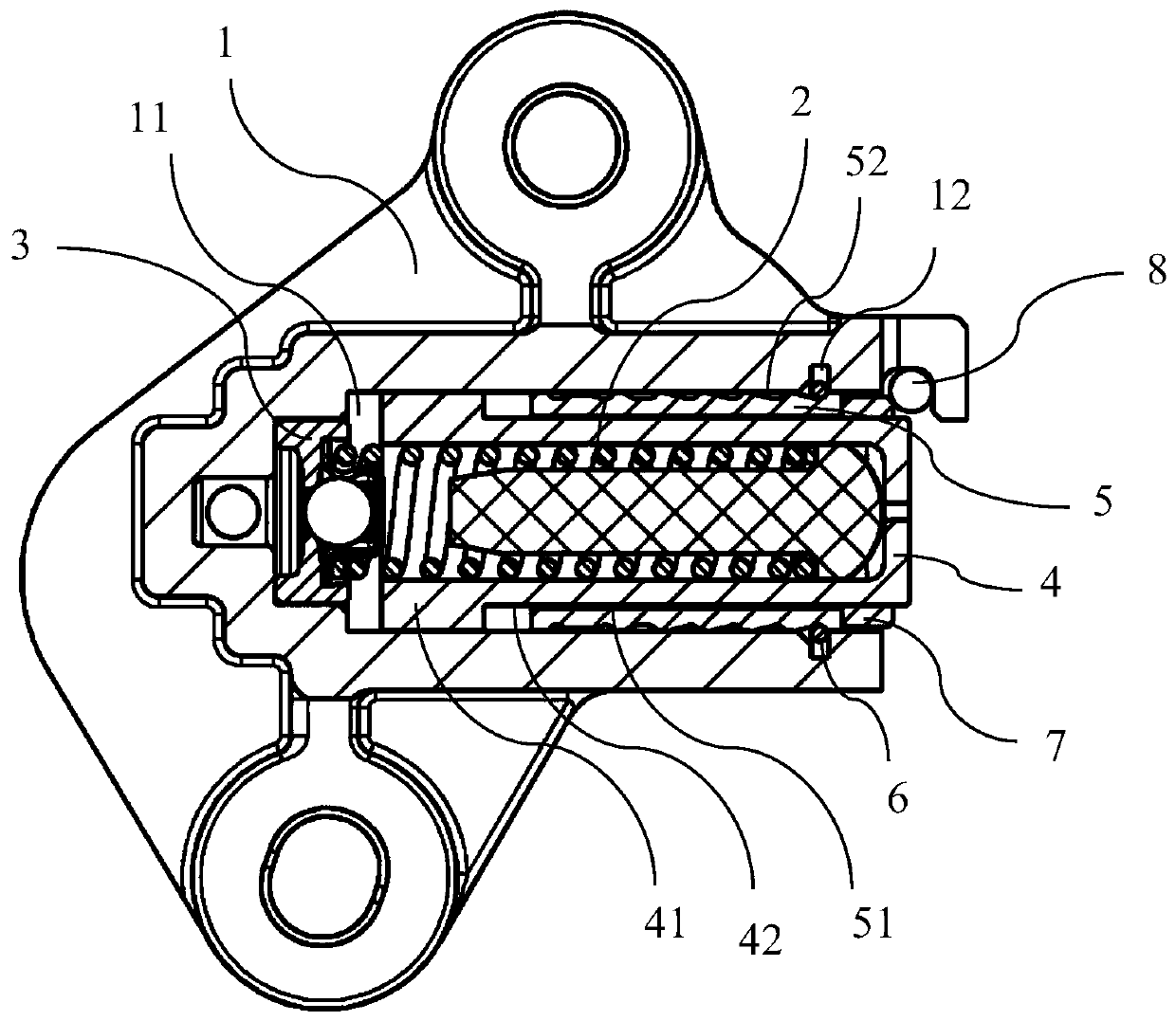
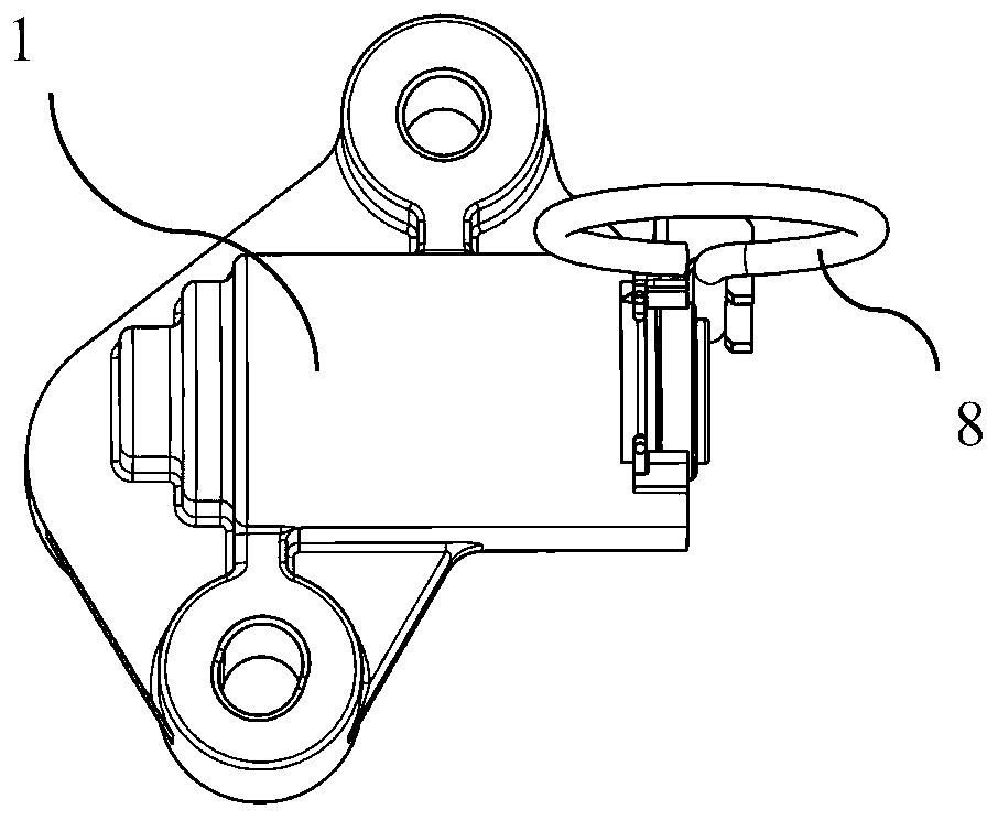
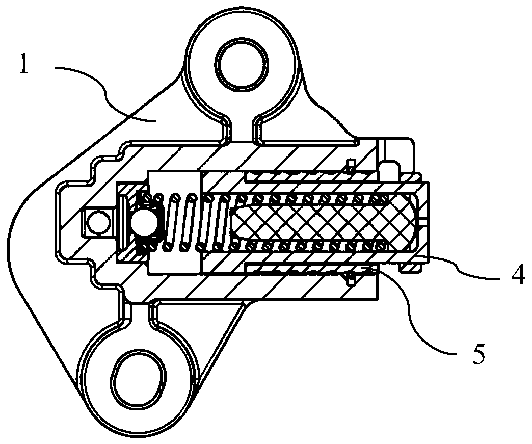
[0030] figure 1 A longitudinal sectional view of a tensioner according to a preferred embodiment of the present invention is shown. The tensioner is configured as a hydraulic tensioner for applying tension to a chain in an engine timing system.
[0031] Such as figure 1As shown, the tensioner includes a housing 1 and a plunger 4 . The housing 1 forms a chamber 11 . The chamber 11 and the plunger 4 adopt a cylindrical structure design in this embodiment. The chamber 11 has an opening on the longitudinal side, ie the axial side. This opening faces a tension arm (not shown) in the engine timing system after the tensioner is assembled to the engine housing. The plunger 4 is at least partially accommodated in the chamber 11 . The plunger 4 is formed with a radially extending collar 41 on the longitudinal end side facing away from the opening of the chamber 11 . Under the combined effect of the spring 2 and the oil delivered to the chamber 11 via the check valve 3, the plunge...
PUM
 Abstract
Description
Claims
Application Information
 - R&D Engineer
- R&D Manager
- IP Professional
- Industry Leading Data Capabilities
- Powerful AI technology
- Patent DNA Extraction
Browse by: Latest US Patents, China's latest patents, Technical Efficacy Thesaurus, Application Domain, Technology Topic, Popular Technical Reports.
© 2024 PatSnap. All rights reserved.Legal|Privacy policy|Modern Slavery Act Transparency Statement|Sitemap|About US| Contact US: help@patsnap.com