Novel dynamic pressure damping sealing structure

A sealing structure and damping technology, which is applied in the direction of engine sealing, engine components, mechanical equipment, etc., can solve the problems of unfavorable rotor bearing system stability, poor sealing ability of screw seal, large circumferential fluid excitation force, etc., to achieve increased Large roughness and damping coefficient, improve the sealing ability and the effect of improving the sealing damping coefficient

Inactive Publication Date: 2020-04-21
XI AN JIAOTONG UNIV
View PDF2 Cites 5 Cited by
  • Summary
  • Abstract
  • Description
  • Claims
  • Application Information

AI Technical Summary

Problems solved by technology

The sealing ability of the spiral seal is proportional to the square of the rotational speed. Therefore, at high rotational speeds, the sealing performance is excellent, and even complete sealing can be achieved. poor
In addition, the leakage flow in the spiral groove of the spiral seal has a large circumferential velocity, which in turn leads to a large circumferential fluid excitation force, which is not conducive to the stability of the rotor bearing system
At present, the operating environment with higher speed, pressure, and temperature has put forward higher requirements for the efficiency and stability of rotating machinery. The commonly used labyrinth seals and spiral seals have gradually failed to meet the needs of modern liquid phase rotating machinery.

Method used


Image

  • Novel dynamic pressure damping sealing structure
  • Novel dynamic pressure damping sealing structure
  • Novel dynamic pressure damping sealing structure

Examples


Embodiment Construction

[0028] The present invention will be described in further detail below in conjunction with the accompanying drawings. The following implementations are only used to illustrate the technical solutions of the present invention more clearly, but not to limit the protection scope of the present invention.

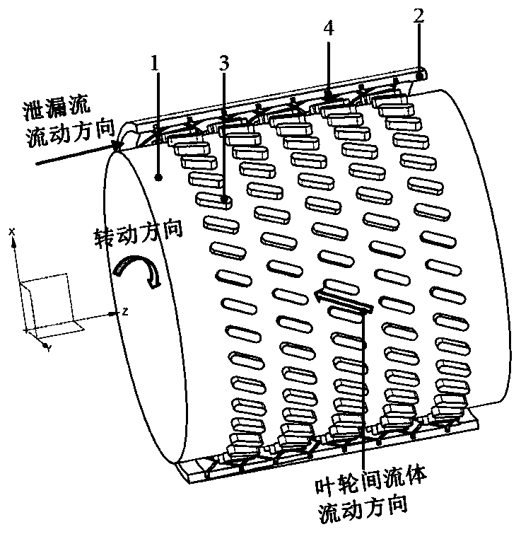
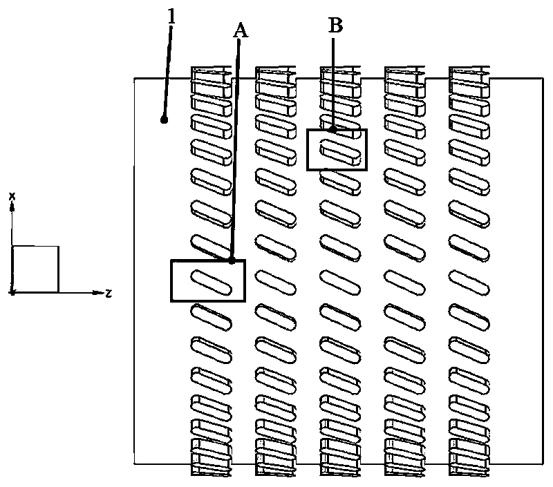
[0029] see Figure 1 to Figure 6 , a new type of dynamic pressure damping seal structure provided by the present invention, including a sealed rotor part 1, and a sealed stator part 2 that is sleeved outside the sealed rotor part 1 and used in conjunction with it; wherein, there are several The micro-impeller 3 capable of generating a dynamic pressure pumping effect, the inner surface of the sealed stator part 2 is provided with a textured structure 4 capable of inhibiting the development of circumferential swirl and increasing the damping coefficient.

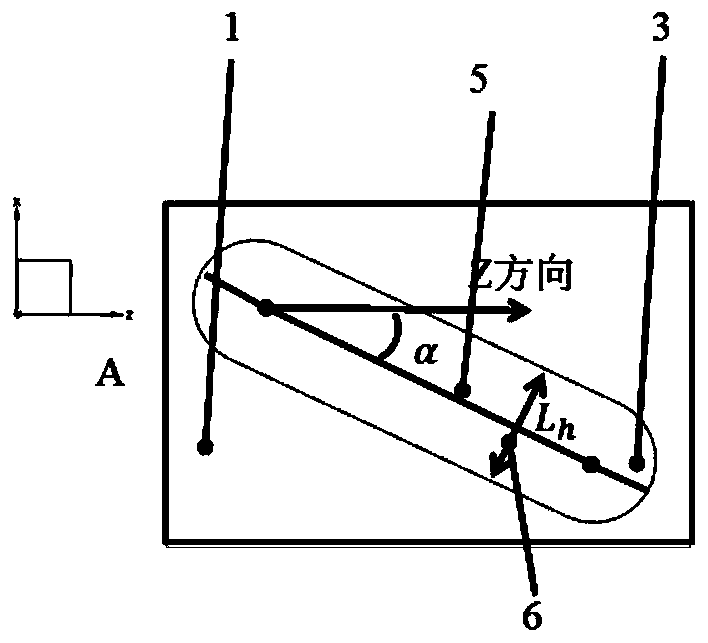
[0030] Further, the micro-impellers 3 arranged on the surface of the sealed rotor part 1 are all inclined towards the rotati...


PUM


Abstract

The invention discloses a novel dynamic pressure damping sealing structure. The structure is characterized by comprising a sealing rotor part and a sealing stator part which is sleeved outside the sealing rotor part and is matched with the sealing rotor part for use, wherein a plurality of micro impellers are arranged on a surface of the sealing rotor part, and a texture structure is arranged on an inner surface of the sealing stator part. When a rotor component rotates, the micro impellers are arranged on a surface of the rotor part, the dynamic pressure pumping effect can be generated, fluidbetween the micro impellers is driven to flow towards the sealed inlet, the axial positive direction leakage flow generated by the pressure difference of a sealing inlet and a sealing outlet is partially counteracted, so purposes of remarkably reducing the sealing leakage flow and improving operation efficiency of the rotary machine are achieved, moreover, the stator part is provided with a texture structure, surface roughness and sealing damping of the stator part can be remarkably improved, circumferential rotational flow development of fluid in a gap between the sealing rotor part and thestator part is effectively restrained, the circumferential component of fluid exciting force is reduced, and thereby a purpose of enhancing system stability is achieved.

Description

technical field [0001] The invention belongs to the technical field of rotating machinery, and in particular relates to a novel dynamic pressure damping sealing structure, which is suitable for the gap between rotor parts and stator parts of rotating machines such as pumps, compressors and turbines. Background technique [0002] Rotary sealing devices are one of the important components of modern rotating machinery such as pumps, compressors, and turbines. The rotary sealing device is usually installed in the gap between the rotor part and the stator part, such as the shaft end and blade tip clearance of the rotating machine, and improves the operating efficiency of the rotating machine by reducing the leakage flow of the working medium from the high pressure end to the low pressure end in the gap. In addition, rotary sealing devices are often used in rotating machinery in petrochemical and other fields to prevent leakage of working fluid and pollute the environment. Theref...

Claims


Application Information

Patent Timeline
Patent Type & Authority Applications(China)
IPC IPC(8): F16J15/40
CPCF16J15/40
Inventor 李志刚方志李军
Owner XI AN JIAOTONG UNIV
Why Eureka
Try Eureka