
Wave velocity microwave phase shift measurement method in combustion-to-detonation process

A combustion-to-detonation and phase-shift measurement technology, which is applied to devices using electrical/magnetic methods, etc., can solve problems such as weakening the confinement strength of the sample tube, deviation of measurement results, and influence on judgment.

Inactive Publication Date: 2020-04-21
XIAN MODERN CHEM RES INST
View PDF4 Cites 2 Cited by
  • Summary
  • Abstract
  • Description
  • Claims
  • Application Information

AI Technical Summary

Problems solved by technology

[0003] There is no unified standard for the type and material of the ionization probe and its manufacturing process, and human factors have a great influence on the quality and response of the probe
The contact state between the probe and the main charge will also affect the response of the probe, thereby affecting the accurate measurement of time parameters
The ionization probe passes through the wall of the sample tube through 8 to 10 through micro-holes to contact the main charge. The existence of multiple micro-holes weakens the confinement strength of the sample tube, making the micro-holes the weak link of the sample tube. Make the measurement results have a large deviation, and even affect the judgment
The ionization probe speed measurement method obtains the average speed between adjacent probes, not the real-time speed, and the amount of data is too small, and the information is not rich enough, which is not conducive to the detailed description of the combustion-to-detonation process

Method used


Image

  • Wave velocity microwave phase shift measurement method in combustion-to-detonation process
  • Wave velocity microwave phase shift measurement method in combustion-to-detonation process
  • Wave velocity microwave phase shift measurement method in combustion-to-detonation process

Examples


Embodiment 1

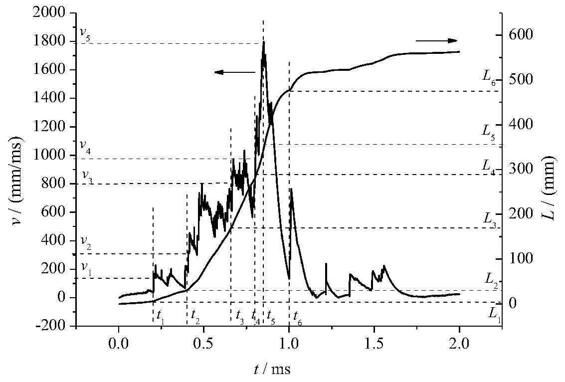
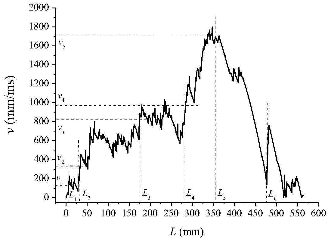
[0067] A method for measuring wave velocity and microwave phase shift in combustion-to-detonation process. The test method includes test preparation, test steps, data processing and result expression.

[0068] 1. Test preparation, including:

[0069] 1.1 Calibration of microwave phase shift test device

[0070] Turn on the system power of the microwave phase-shift testing device, and after preheating, the microwave phase-shift testing device performs normalization processing on the collected echoes. Use a special tool to cut off the known length of the microwave sensor probe to avoid phase ambiguity. The length cut each time should be smaller than the guided wavelength in the probe. Use a measuring tool with an accuracy better than 0.5mm to measure the length of the cut probe. Compare the test distance given by the phase shift test device to obtain the distance measurement accuracy; control the phase of the beacon output signal to obtain the phase change rate corresponding to...


PUM


Abstract

The invention discloses a wave velocity microwave phase shift measurement method in a combustion-to-detonation process. The wave velocity microwave phase shift measurement method solves the problems that an existing method can only obtain an average velocity and is poor in measurement precision. When explosives and charges are combusted or detonated, the end surface of a probe of a microwave sensor can synchronously move along with the advancing of the wave front due to high-temperature burning, thus doppler frequency shift and phase change occur between echo signals and transmitted signals, Doppler speed and phase information of the wave front at each moment are obtained through processing, and then the propagation speed of the wave front and the corresponding moment and displacement in the combustion-to-detonation process are obtained. The wave velocity microwave phase shift measurement method is high in sampling frequency and rich in obtained information, and has the advantages of high measurement precision and good safety performance. The wave velocity microwave phase shift measurement method is suitable for measuring the wave velocity and the corresponding moment and displacement in the combustion-to-detonation process of solid explosive and charges based on a sample tube method, and are further suitable for measuring the linear combustion velocity and the corresponding moment and displacement of other solid fuels.

Description

technical field [0001] The invention relates to a microwave phase shift measurement method for wave velocity in the combustion-to-detonation process, which is suitable for the technical field of wave velocity measurement in the combustion-to-detonation process of solid explosives and charges based on the sample tube method. Background technique [0002] During the transition from combustion to detonation of propellants and explosives, the measurement of wave velocity is currently more commonly used with ionization probes, which is to arrange a series of probes at equal intervals on a special sample tube, and use ion probes to track the ionization surface ( Combustion flame front, detonation front) to detect the burning velocity and detonation velocity in the sample tube. [0003] There is no uniform standard for the type and material of the ionization probe and its manufacturing process, and human factors have a great influence on the quality and response of the probe. The ...

Claims


Application Information

Patent Timeline
IPC IPC(8): G01P3/50
CPCG01P3/50
Inventor 仪建华李海建秦钊王彦杰张鹏王长健赵凤起许毅孙志华
Owner XIAN MODERN CHEM RES INST
Learn More