Signal arrival angle estimation method and device and computer readable storage medium

A technology of angle of arrival and signal, applied in the field of signal processing, can solve problems such as small amount of calculation, received signal jitter, large amount of calculation, etc., and achieve the effect of reducing estimation error

Active Publication Date: 2020-04-21
TELINK SEMICON SHANGHAI
View PDF16 Cites 6 Cited by
  • Summary
  • Abstract
  • Description
  • Claims
  • Application Information

AI Technical Summary

Problems solved by technology

[0003] Signal angle of arrival estimation has always been an important research topic in the field of array signal processing, and has been widely used in radar, wireless communication and other fields. Among traditional signal angle of arrival estimation algorithms, MUSIC algorithm and ESPRIT algorithm are commonly used. It decomposes the covariance matrix of the array received data into mutually orthogonal signal subspaces and noise subspaces, and uses the direct relationship between the signal and noise subspaces to estimate the angle of arrival of the signal. It is estimated that the eigenvalue decomposition of the covariance matrix is ​​required, so the amount of calculation required is large
[0004] In addition, it is also possible to determine the phase angle corresponding to each array element in the antenna under different incident angles according to the antenna arrangement, obtain the standard antenna direction in the ideal situation, and then compare the actual received signal with the standard antenna direction at different incident angles After estimating the angle of arrival, although this method has a small amount of calculation, it is easy to cause a large estimation error due to the jitter of the received signal

Method used


Image

  • Signal arrival angle estimation method and device and computer readable storage medium
  • Signal arrival angle estimation method and device and computer readable storage medium
  • Signal arrival angle estimation method and device and computer readable storage medium

Examples


Embodiment Construction

[0030] Exemplary embodiments of the present disclosure will be described in more detail below with reference to the accompanying drawings. Although exemplary embodiments of the present disclosure are shown in the drawings, it should be understood that the present disclosure may be embodied in various forms and should not be limited to the embodiments set forth herein. Rather, these embodiments are provided for more thorough understanding of the present disclosure and to fully convey the scope of the present disclosure to those skilled in the art.

[0031] In the present invention, it should be understood that terms such as "comprising" or "having" are intended to indicate the presence of features, numbers, steps, acts, components, parts or combinations thereof disclosed in the specification, and are not intended to exclude one or multiple other features, numbers, steps, acts, parts, parts or combinations thereof.

[0032] In addition, it should be noted that, in the case of n...


PUM


Abstract

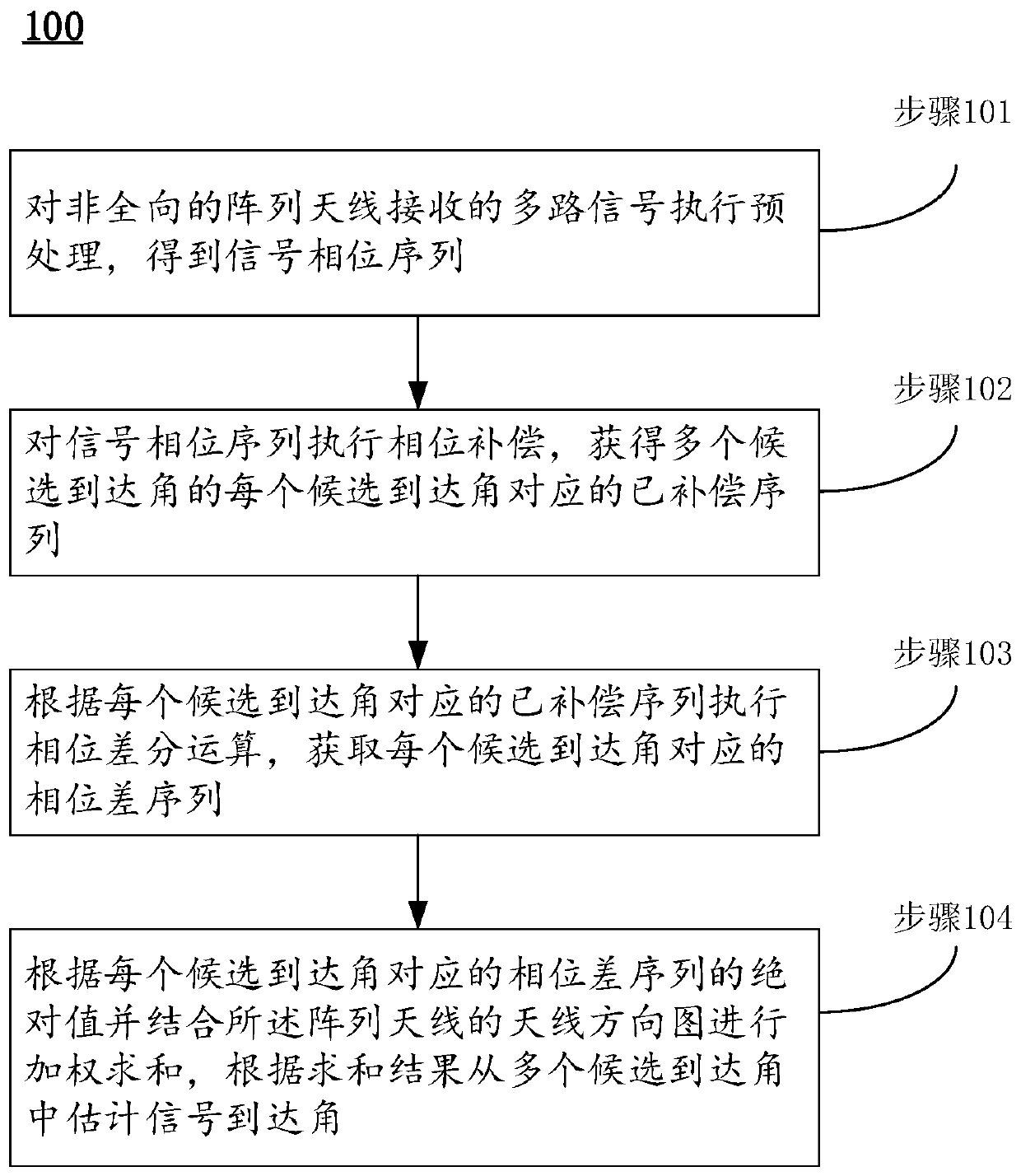
The invention provides a signal arrival angle estimation method and device and a computer readable storage medium. The method comprises the steps: carrying out preprocessing of a plurality of paths ofsignals received by a non-omnidirectional array antenna to obtain a receiving phase sequence; performing phase compensation on the received phase sequence to obtain a compensation phase sequence corresponding to each of the plurality of candidate arrival angles; executing phase difference operation according to the compensation phase sequence corresponding to each candidate arrival angle to obtain a phase difference sequence corresponding to each candidate arrival angle; and performing weighted summation according to the absolute value of the phase difference sequence corresponding to each candidate arrival angle in combination with an antenna pattern of the array antenna, and estimating a signal arrival angle from the plurality of candidate arrival angles according to a summation result.With the method, the estimation error caused by the jitter of the received signal can be reduced.

Description

technical field [0001] The invention belongs to the field of signal processing, and in particular relates to a signal arrival angle estimation method, device and computer-readable storage medium. Background technique [0002] This section is intended to provide a background or context for implementations of the invention that are recited in the claims. The descriptions herein are not admitted to be prior art by inclusion in this section. [0003] Signal angle of arrival estimation has always been an important research topic in the field of array signal processing, and has been widely used in radar, wireless communication and other fields. Among traditional signal angle of arrival estimation algorithms, MUSIC algorithm and ESPRIT algorithm are commonly used. It decomposes the covariance matrix of the array received data into mutually orthogonal signal subspaces and noise subspaces, and uses the direct relationship between the signal and noise subspaces to estimate the angle ...

Claims


Application Information

Patent Timeline
Patent Type & Authority Applications(China)
IPC IPC(8): G01S3/14G01S3/16G01S3/46H04B7/08
CPCG01S3/14G01S3/16G01S3/46H04B7/0842
Inventor 黄海力
Owner TELINK SEMICON SHANGHAI
Why Eureka
Try Eureka