
Direct-current power distribution network fault isolation and recovery method, device and computer equipment

A DC distribution network and fault isolation technology, applied in the direction of DC network circuit devices, circuit devices, emergency protection circuit devices, etc., can solve DC distribution network power outages, non-faulty section switch trips, faulty sections and non-faulty sections Section isolation is difficult to achieve the effect of reducing impact, achieving effective isolation, and avoiding simultaneous overlapping of fault points

Active Publication Date: 2020-04-21
ELECTRIC POWER RES INST OF GUANGDONG POWER GRID
View PDF2 Cites 2 Cited by
  • Summary
  • Abstract
  • Description
  • Claims
  • Application Information

AI Technical Summary

Problems solved by technology

[0006] The embodiment of the present invention provides a DC distribution network fault isolation recovery method, device and computer equipment, which are used to solve the problem of difficulty in isolating the faulty section from the non-faulty section after a fault occurs in the existing DC distribution network, and the non-faulty section The switch of the switch may also trip, resulting in technical problems of large-scale power outages in the DC distribution network

Method used


Image

  • Direct-current power distribution network fault isolation and recovery method, device and computer equipment
  • Direct-current power distribution network fault isolation and recovery method, device and computer equipment
  • Direct-current power distribution network fault isolation and recovery method, device and computer equipment

Examples


Embodiment 1

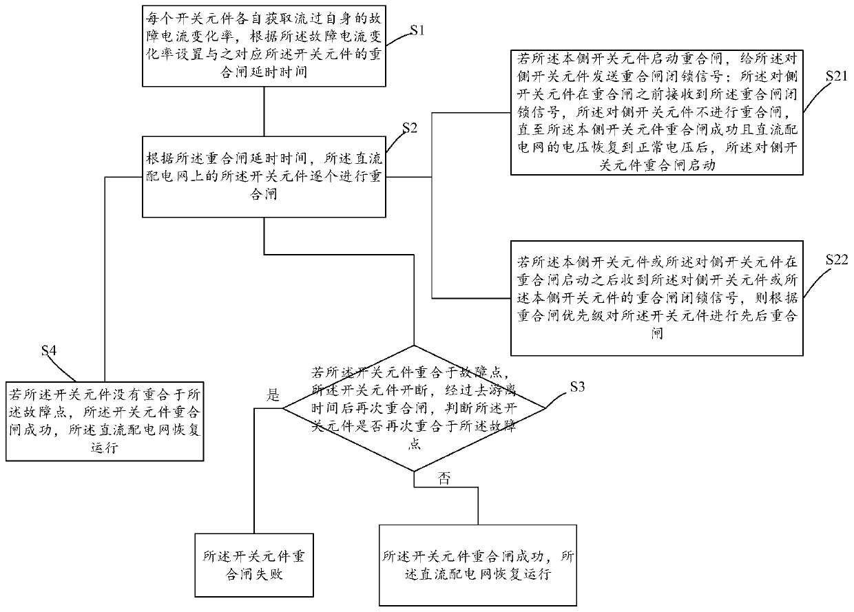
[0059] figure 1 It is a flow chart of the steps of the DC distribution network fault isolation and recovery method described in the embodiment of the present invention.

[0060] like figure 1 As shown, the embodiment of the present invention provides a DC distribution network fault isolation and recovery method, which is applied to a faulty DC distribution network, and aims to realize the protection action when a DC fault occurs in the DC distribution network and the automatic recovery after the switching element trips. Orderly reclosing ensures effective isolation of permanent faults and reliable recovery of the DC distribution network. In the embodiment of the present invention, it is aimed at the DC distribution network that adopts single-ended voltage or current characteristic quantity to configure the main protection. When a DC fault occurs, the DC voltage mutation value meets the threshold value to start. direction) reaches the current setting value, the protection fas...

Embodiment 2

[0102] Figure 5 It is a frame diagram of the DC distribution network fault isolation and recovery device described in the embodiment of the present invention.

[0103] like Figure 5 As shown, the embodiment of the present invention provides a DC distribution network fault isolation recovery device, which is applied to a faulty DC distribution network, including:

[0104] The reclosing delay time acquisition unit 10 is used for each switching element to obtain the rate of change of the fault current flowing through itself, and set the reclosing delay time corresponding to the switching element according to the rate of change of the fault current;

[0105] Executing unit 20, used for each of the switching elements on the DC power distribution network to reclose one by one according to the staggered order of the reclosing delay time;

[0106] The first judging unit 30 is used to judge whether the switching element overlaps with the fault point;

[0107] The second judging un...

Embodiment 3

[0124] An embodiment of the present invention provides a computer device, including a processor and a memory;

[0125] The memory is used to store program codes and transmit the program codes to the processor;

[0126] The processor is configured to execute the above-mentioned DC power distribution network fault isolation and recovery method according to the instructions in the program code.

[0127] It should be noted that the processor is configured to execute the steps in the above-mentioned embodiment of a DC power distribution network fault isolation and recovery method according to the instructions in the program code, for example figure 1 Steps S1 to S4 are shown. Alternatively, when the processor executes the computer program, the functions of the modules / units in the above-mentioned device embodiments are realized, for example Figure 5 Function of units 10 to 50 shown.

[0128] Exemplarily, a computer program can be divided into one or more modules / units, and one ...


PUM


Abstract

The embodiment of the invention relates to a direct-current power distribution network fault isolation and recovery method, a direct-current power distribution network fault isolation and recovery device and computer equipment. The staggered reclosing of switching elements is realized through setting the reclosing delay time of the switching elements in direct proportion to the change rate of fault current, and therefore, the effective isolation of a fault point can be achieved, and the operation of a direct-current power distribution network is resumed. Switching elements in the same direct-current line section send reclosing locking signals to switching elements on the opposite side, so that the switching elements in the same direct-current line section are successively reclosed, and therefore, the condition that the switching elements on the two sides coincide with the fault point at the same time can be avoided, and impact on a direct-current power distribution network is reduced.According to the prior art, after a direct-current power distribution network breaks down, a fault section and a non-fault section are difficult to isolate from each other, the switch of the non-faultsection may trip off, and as a result, the technical problem of the large-area power failure of the direct-current power distribution network may be brought about. However, with the device, method and computer equipment of the invention adopted, the above technical problem in the prior art can be solved.

Description

technical field [0001] The invention relates to the technical field of DC power distribution systems, in particular to a method, device and computer equipment for fault isolation and restoration of a DC power distribution network. Background technique [0002] The DC distribution network is relative to the AC distribution network, and it provides the load with the DC bus. The DC load can be directly powered by the DC bus, while the AC load needs to be powered by the inverter device. With the increase in the installed capacity of new energy and the proportion of DC loads, DC power distribution will have great advantages. [0003] DC line protection is an important link to ensure the safe and stable operation of DC distribution network. The DC distribution network has the characteristics of a large number of lines but a short length, small damping and fast fault propagation. Therefore, higher requirements are put forward for the DC fault detection and DC line protection tech...

Claims


Application Information

Patent Timeline
Patent Type & Authority Applications(China)
IPC IPC(8): H02J1/00H02H7/26H02H3/06
CPCH02H3/06H02H3/066H02H7/261H02H7/268H02J1/00
Inventor 马燕君安然然刘军梁晓兵张远王奕
Owner ELECTRIC POWER RES INST OF GUANGDONG POWER GRID
Learn More