
Three-dimensional city models and shadow mapping to improve altitude fixes in urban environments

A high-level, indoor environment technology, applied in satellite radio beacon positioning systems, instruments, measuring devices, etc., can solve problems such as aggravation, poor performance, mobile device location accuracy and solution usability, and achieve the goal of improving high-level positioning Effect

Pending Publication Date: 2020-04-21
APPLE INC
View PDF8 Cites 4 Cited by
  • Summary
  • Abstract
  • Description
  • Claims
  • Application Information

AI Technical Summary

Problems solved by technology

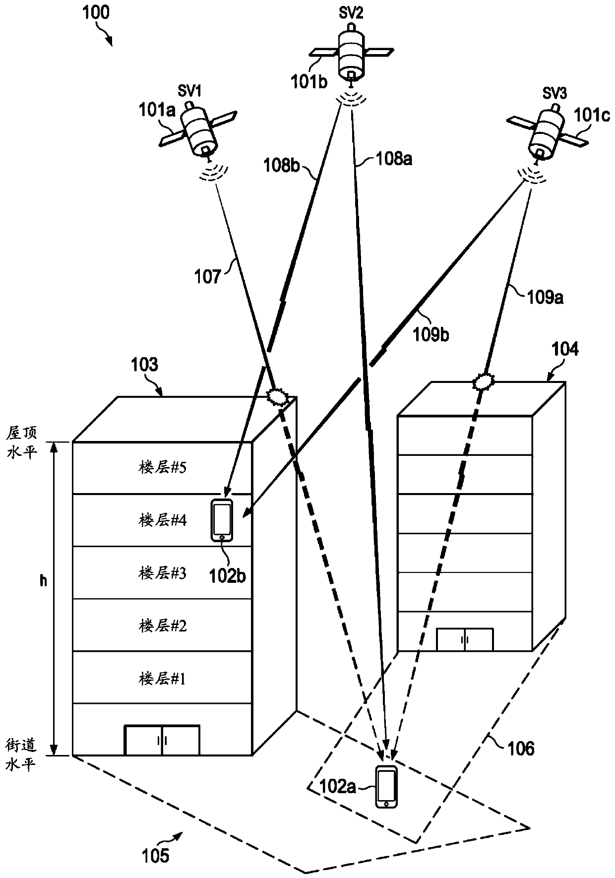
In challenging GNSS signal environments, such as "urban canyons" with tall buildings and narrow streets, mobile device location accuracy and solution availability may perform poorly
Poor performance is exacerbated in cross-street direction and height as line-of-sight (LOS) GNSS signals are more likely to be blocked by buildings or other tall structures

Method used


Image

  • Three-dimensional city models and shadow mapping to improve altitude fixes in urban environments
  • Three-dimensional city models and shadow mapping to improve altitude fixes in urban environments
  • Three-dimensional city models and shadow mapping to improve altitude fixes in urban environments

Examples


example 3D

[0035] Example 3D Candidate Position Grid (CPG)

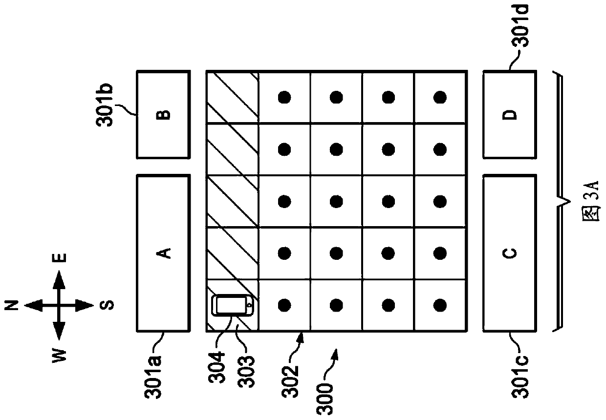
[0036] Once the 2D CPG is generated, vertically extend all or part of the 2D CPG to create a multi-layered 3D CPG, such as Figure 3B shown. The vertical spacing between layers in a 3D CPG may or may not be equidistant, and may be the same as or different from the horizontal spacing (eg, 2-3 meters). In an embodiment, the number of floors and the vertical spacing between floors may be based on the tallest building in the area. The coverage area of ​​the 3D CPG may vary based on an assessment of the quality of the received GNSS signal. For example, to reduce computation, it is not necessary to extend all candidate positions in the 2D CPG in the vertical direction. Instead, certain candidate locations may be selected for vertical extension based on satellite geometry and their proximity to the candidate indoor environment.

[0037] Figure 3A is a top plan view of an example 2D CPG according to an embodiment. In the examp...


PUM


Abstract

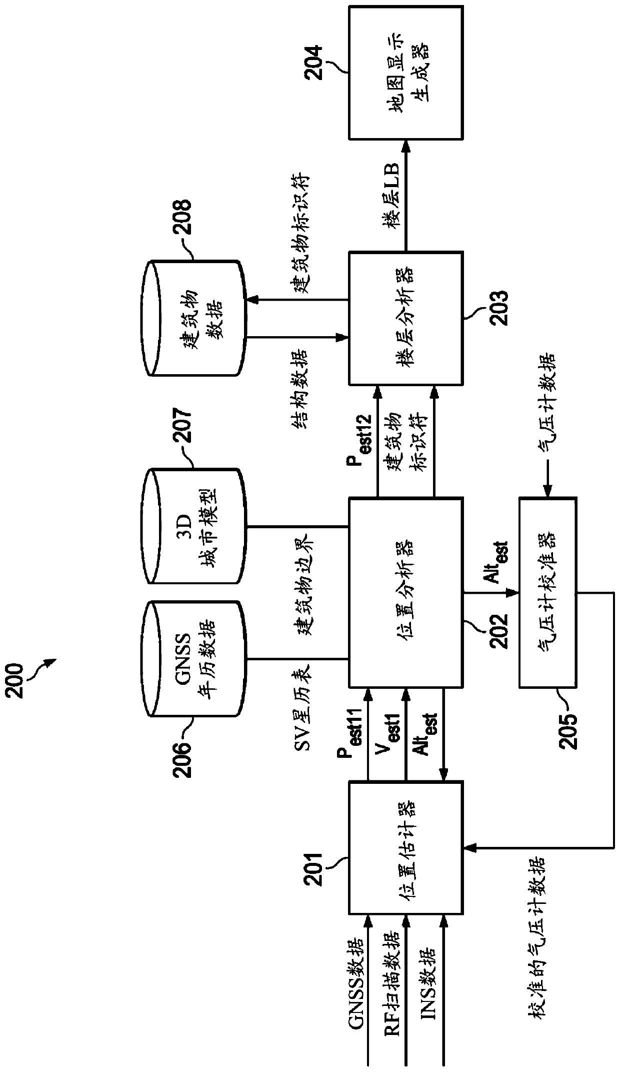
The disclosed embodiments use 3D city models and shadow mapping to improve altitude fixes in urban environments. In an embodiment, a method comprises: generating a set of three-dimensional (3D) candidate positions in a geographic area of interest; predicting global navigation satellite system (GNSS) signal visibility at selected ones of the 3D candidate positions; receiving GNSS signals at a current location of the mobile device; determining observed satellite visibility based on the received GNSS signals; comparing the predicted satellite visibility with the observed satellite visibility; determining a position fix based on a result of the comparing; determining an indoor environment where the mobile device is located based at least on an altitude component of the position fix; obtainingstructural data for the identified indoor environment; and determining a floor lower bound for the current location of the mobile device based on the altitude component and the structural data.

Description

[0001] Cross References to Related Applications [0002] This patent application claims priority to U.S. Patent Application 15 / 719,470, filed September 28, 2017, which is hereby incorporated by reference in its entirety. technical field [0003] The present disclosure generally relates to position determination using radio signals. Background technique [0004] Many mobile devices, such as smartphones, tablets, and wearable devices (eg, smart watches), have navigation applications that depend on Global Navigation Satellite System (GNSS) signals. In challenging GNSS signal environments, such as "urban canyons" with tall buildings and narrow streets, the position accuracy and solution availability of mobile devices can suffer. Poor performance is exacerbated in cross-street directions and heights because line-of-sight (LOS) GNSS signals are more likely to be blocked by buildings or other tall structures. Contents of the invention [0005] The disclosed embodiments use 3D ...

Claims


Application Information

Patent Timeline
IPC IPC(8): G01S19/40G01S19/42G01S19/22
CPCG01S19/22G01S19/42G01S19/40G01S19/28G01S19/45
Inventor K·G·乔克拉G·D·麦高根R·梅尔
Owner APPLE INC
Learn More