Heart valve stent and heart valve prosthesis

A heart valve and prosthesis technology, applied in the field of interventional medical prosthesis, can solve the problems of atrioventricular block, prone to displacement, and limited ability of valve prosthesis to prevent paravalvular leakage, so as to prevent atrioventricular block The effect of stagnation and prevention of paravalvular leak

Pending Publication Date: 2020-04-24
SHANGHAI MICROPORT CARDIOFLOW MEDTECH CO LTD
View PDF0 Cites 2 Cited by
  • Summary
  • Abstract
  • Description
  • Claims
  • Application Information

AI Technical Summary

Problems solved by technology

[0006] 1. After the stent is released in the body, it is easy to shift;
[0007] 2. The valve prosthesis has limited ability to preven

Method used


Image

  • Heart valve stent and heart valve prosthesis
  • Heart valve stent and heart valve prosthesis
  • Heart valve stent and heart valve prosthesis

Examples


Embodiment Construction

[0035] The present invention will be further described below in conjunction with the accompanying drawings and embodiments.

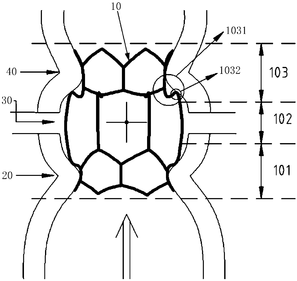
[0036] figure 1 It is a structural schematic diagram of a heart valve stent in an embodiment of the present invention.

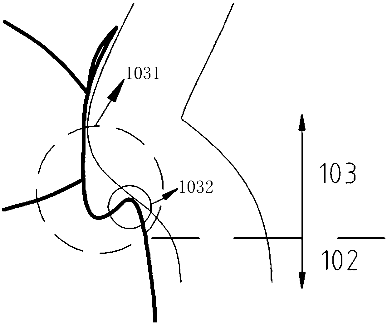
[0037] Heart valve prosthesis provided by the present invention comprises support 10, valve leaflet and skirt (not shown in the figure), please refer to figure 1 , the bracket 10 includes a bracket body and a limiting structure 1031 connected to the bracket body. The stent body is composed of interconnected grid structure units, and the stent body is divided into an inflow channel 101, a transition section 102 and an outflow channel 103 in the axial direction; according to the direction of blood flow, the transition section 102 is located downstream of the inflow channel 101, Outflow channel 103 is located downstream of transition section 102 . The inflow channel 101 corresponds to the part where blood flows into the prosthesis whe...


PUM


Abstract

The invention discloses a heart valve stent and a heart valve prosthesis. The heart valve stent comprises a stent main body, which comprises mutually connected grid structure units, wherein the stentmain body is divided into an inflow channel, a transition section and an outflow channel in the axial direction, the inflow channel, the transition section and the outflow channel are connected in sequence, the stent further comprises a limiting structure connected with the stent main body, and the limiting structure is distributed on the outflow channel or the transition section in the circumferential direction, and is provided with a first projection part for limiting the stent from moving from the inflow channel to the outflow channel. According to the invention, the limiting structure is arranged on the outflow channel of the stent, so that the stent can be prevented from moving towards the outflow channel under the scouring of blood flow; the inflow channel of the stent is arranged toadapt to the shape of the native tissue, and the outer skirt edge is arranged in the circumferential direction of the outer side of the inflow channel at the position attached to the native tissue, so that perivalvular leakage can be effectively prevented while the valve is prevented from moving towards the inflow channel; and the size of the inflow channel of the stent can be small so as to effectively prevent atrioventricular block, and the size of the outflow channel can be small so as to reduce the compression on the aorta.

Description

technical field [0001] The invention relates to an interventional medical prosthesis, in particular to a heart valve support and the prosthesis. Background technique [0002] With the advent of the global aging society, aortic valve disease has become one of the common cardiovascular diseases. In my country, the incidence rate is 2%-5%, and in European and American countries after coronary heart disease and hypertension, it ranks third. Thousands of patients benefit from surgical aortic valve replacement each year, but even in developed countries, a large number of patients with severe aortic valve disease still die due to advanced disease, advanced age, and the presence of multiple comorbidities. Unable to accept surgical treatment, the emergence of percutaneous artificial aortic valve products and the continuous improvement of product performance have undoubtedly brought good news to these patients and provided an effective treatment method. [0003] In 2002, Cribier et ...

Claims


Application Information

Patent Timeline
IPC IPC(8): A61F2/24
CPCA61F2/2412A61F2/2418A61F2/246A61F2/24
Inventor 刘世红赵婧陈国明李雨
Owner SHANGHAI MICROPORT CARDIOFLOW MEDTECH CO LTD
Why Eureka
Try Eureka