A kind of atrioventricular valve support and its delivery system for puncture implantation

A technique for an atrioventricular valve and a delivery system, which is applied to the field of an atrioventricular valve stent for puncture implantation and its delivery system, and achieves the effects of high success rate, prevention of paravalvular leakage, and convenient and safe implantation operation.

Active Publication Date: 2018-11-06
SHANGHAI TONGJI HOSPITAL
View PDF5 Cites 0 Cited by
  • Summary
  • Abstract
  • Description
  • Claims
  • Application Information

AI Technical Summary

Problems solved by technology

[0014] The purpose of the present invention is to provide an atrioventricular valve stent for puncture insertion, which solves the technical problems existing in the structure and embedment process of the above-mentioned existing valve stent

Method used


Image

  • A kind of atrioventricular valve support and its delivery system for puncture implantation
  • A kind of atrioventricular valve support and its delivery system for puncture implantation
  • A kind of atrioventricular valve support and its delivery system for puncture implantation

Examples


Embodiment 1

[0074] Example 1: Puncture and placement through the left ventricular apical approach

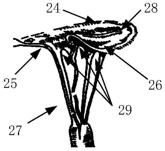
[0075] The surgical approach for valve stent placement via the left ventricular apical approach is as follows: Figure 6 As shown in the figure, the valve support 10 is partially released, and the fixing arm is opened to hook the anterior leaflet 25 and the posterior leaflet 26 of the mitral valve;

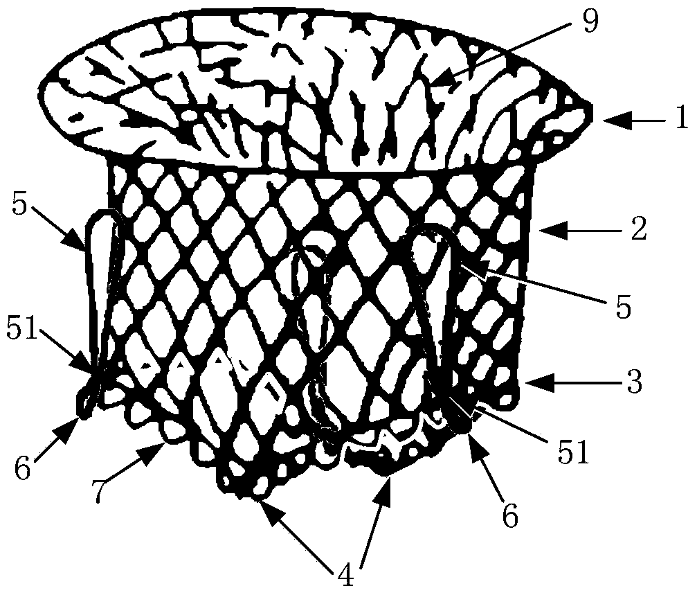
[0076] Before the operation, the valve stent 10 is first compressed into the delivery system, wherein the front end of the valve stent 10 is the left atrial side fixed part 1 of the expandable outer stent 9, and is compressed in the head end sheath tube 13 at the head end of the inner core 17, and the valve stent The rear end of 10 includes the left ventricle side fixing part 3 of the expandable outer stent 9, the barb part 6 of the fixing arm 5 and the anti-reflux edge 4 between valves, which are compressed in the outer sheath tube 14 of the delivery system, and the pulling wire 15 Put it o...

Embodiment 2

[0082] Example 2: Through the left ventricular apex approach, the fixed part 1 on the left atrial side releases the expansion first

[0083] The embodiment of valve stent implantation through the left ventricular apex approach, and the expansion of the fixed part 1 on the left atrial side is released first Figure 11 As shown in the figure, the valve support 10 is partially released, the fixing arm is opened to hook the anterior leaflet 25 and the posterior leaflet 26 of the mitral valve, and the left atrial side fixing part 1 is opened. In this embodiment, the first and second steps of the valve support release process are exactly the same as in Embodiment 1, but the fixed arm 5 released after the valve support 10 is opened to hook the anterior leaflet 25 and the rear leaflet of the mitral valve. After the valve leaflet 26, the front part of the valve support 10 is released from the head end sheath tube 13 by pushing the inner core 17, so that the left atrium side fixing pa...

Embodiment 3

[0084] Example 3: Puncture placement through the left atrium

[0085] Figure 12 It is an embodiment of the surgical approach for valve stent implantation through the left atrium approach, and the insertion direction of the valve stent 10 in the delivery system is as follows: Figure 12 As shown in the figure, the valve support 10 is partially released, and the fixed arm is opened to hook the anterior valve leaflet 25 and the posterior valve leaflet 26 of the mitral valve; the left atrial side of the valve support 10 is placed at the proximal end of the delivery system, and the external The left atrial side fixing part 1 of the stent 9 is compressed in the outer sheath tube 14 as the rear end of the valve stent 10; and the intervalvular anti-reflux edge 4, as the front end of the valve stent 10 is compressed into the head end sheath tube 13 of the inner core head end 12; the pulling wire 15 is set on the edge of the bracket of the left atrial side fixing part 1, and the pul...


PUM


Abstract

An atrioventricular valve stent for puncture placement and a conveying system thereof relate to the prosthesis capable of being placed in human body, and especially relate to a atrioventricular valve stent and a placement operation apparatus thereof; the atrioventricular valve stent comprises an expansible outer support, a valve and a plurality of fixed arms; an inverted hook portion of the fixed arm and the fixed arm can form a seesaw lever; a draw line pulls the inverted portion to drive the fixed arm to expand, thus hooking a bicuspid valve leaflet, and fixing the valve stent on an atrioventricular valve; an inter-valve anti-backflow edge corresponding to the valve leaflet boundary can seal the boundary slit so as to prevent valve peripheral backflow; the conveying system comprises an outer sheath canal, a core and a push rod, wherein the core head is connected with the head sheath canal; the valve stent front end is compressed in the head sheath canal, and the rear end is compressed in the outer sheath canal; the push rod can push the valve stent outside the outer sheath canal in a multi-stage section mode, and release the stent; the draw line connected with the valve stent is matched with the inter-valve anti-backflow edge; the valve stent is easy to place in, adjust and retrieve, convenient and safe in operation, high in succeed rate, and can effectively prevent valve peripheral leakage.

Description

technical field [0001] The invention relates to a prosthesis that can be placed in the body, in particular to a heart valve support and surgical instruments for placing it into the body. Background technique [0002] Surgical valve replacement is the main method for the treatment of patients with mitral valve disease. The technology of valve replacement surgery is mature, reliable and effective. The mitral valve is anatomically very complex, as figure 1 As shown, the annulus 24 is oval, the diameter of the annulus 24 is relatively soft, and the activity is large. The valve is bileaflet type with chordae and papillary muscles 27 under the valve. The positioning of the interventional artificial valve needs to be in the esophagus. It can be performed under the guidance of ultrasound or X-ray fluoroscopy, and it is difficult to fix. The chordae or papillary muscles may be injured during the implantation process, and paravalvular leaks are easily formed after surgery. Once the...

Claims


Application Information

Patent Timeline
Patent Type & Authority Patents(China)
IPC IPC(8): A61F2/24
CPCA61F2/2409A61F2/2418A61F2/2466A61F2220/0008
Inventor 周永新郭峻莉梅运清张智强单颖军
Owner SHANGHAI TONGJI HOSPITAL
Why Eureka
Try Eureka