Prosthetic valve and prosthetic valve system

A technology of artificial valve and main body, which is applied in the field of artificial valve and artificial valve system, and can solve problems such as artificial valve instability

Pending Publication Date: 2022-05-20
SHENZHEN LIFEVALVE MEDICAL SCI CO LTD
View PDF0 Cites 0 Cited by
  • Summary
  • Abstract
  • Description
  • Claims
  • Application Information

AI Technical Summary

Problems solved by technology

[0006] Based on this, it is necessary to provide an artificial valve to solve the problem of instability after artificial valve implantation in the prior art

Method used


Image

  • Prosthetic valve and prosthetic valve system
  • Prosthetic valve and prosthetic valve system
  • Prosthetic valve and prosthetic valve system

Examples


no. 1 example

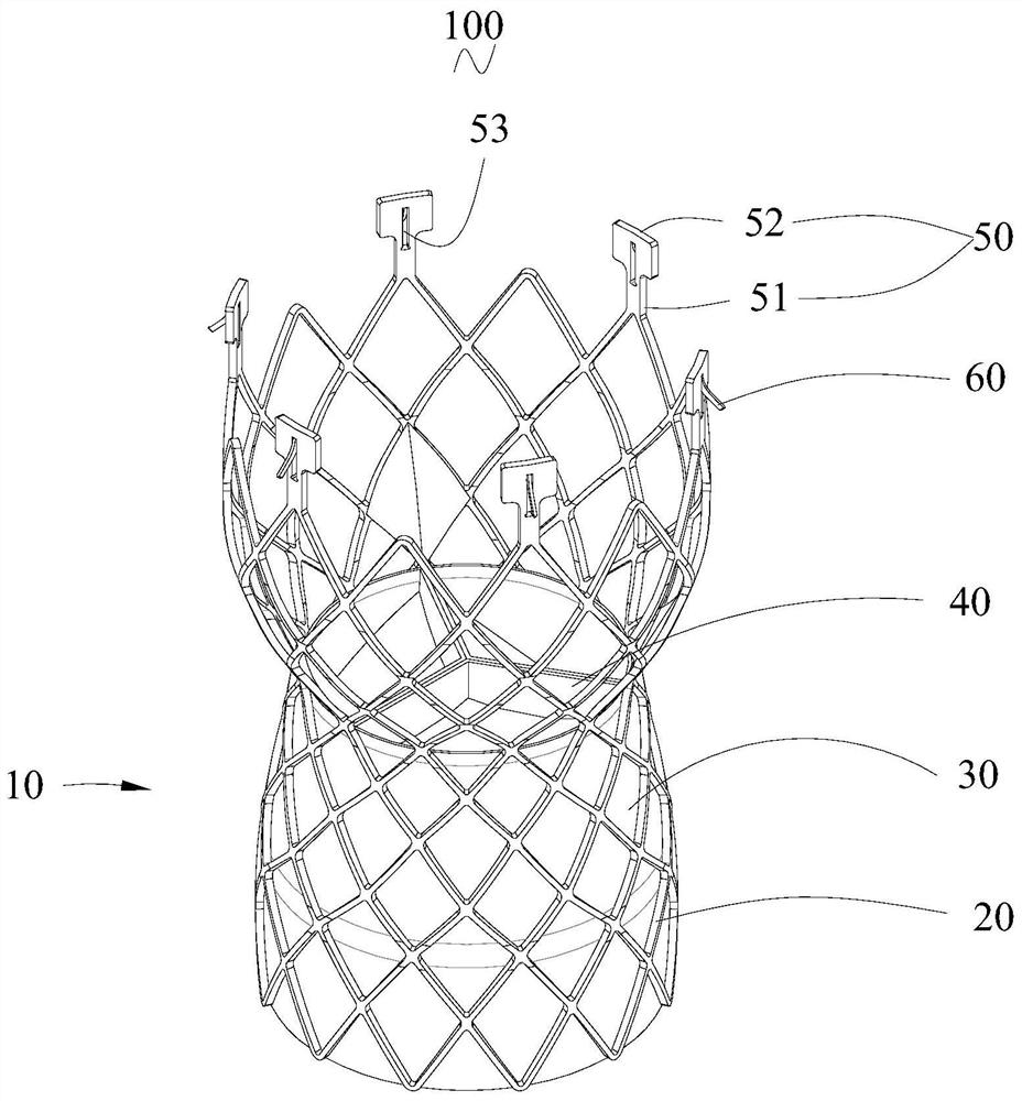
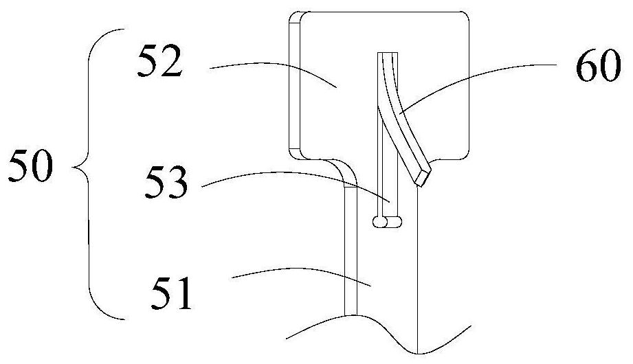
[0040] see figure 1 and figure 2 , the present embodiment provides an artificial valve system 100, including an artificial valve 10 and a delivery device 90 (the delivery device 90 is in figure 1 and figure 2 not shown in the Figure 5 shown in ), the artificial valve 10 is delivered into the human body through the delivery device 90 for release, and the artificial valve 10 and the delivery device 10 are detachably connected. The artificial valve 10 includes a main frame 20 , a skirt 30 , an artificial valve leaflet 40 , a connection structure 50 and an anchor 60 . The main body bracket 20 can provide an installation base for the artificial valve leaflet 40, the skirt 30, and the connecting structure 50. The artificial valve leaflet 40, the skirt 30, and the connecting structure 50 are all connected to the main body bracket 20, and the anchor 60 is arranged on the connecting structure 50. .

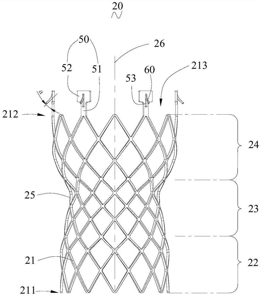
[0041] Specifically, see figure 2 , the main body stent 20 includes a plural...

no. 2 example

[0061] see Figure 7 The difference between this embodiment and the first embodiment is that the specifications of the axial spacing between the plurality of anchors 60 and the proximal end of the main body stent 20 are at least two, and are similar to the proximal end of the main body stent 20. A plurality of anchors 60 with equal axial spacing between the ends are located on the same plane. That is, the plurality of anchors 60 in this embodiment are distributed on at least two planes. When the anchor piece 60 penetrates into the tissue, the stress points where the anchor piece 60 and the tissue are anchored are distributed in at least two planes with different axial distances from the proximal end of the main body bracket 20, and are different from all the stressed points. Compared with the fact that the force points are only distributed in one plane, it can increase the anti-swing ability of the artificial valve 10 in the corresponding section of the anchor 60, thereby imp...

no. 3 example

[0067] see Figure 9 , the main body stent 20 has a first side 27 and a second side 28 opposite to the first side 27. When the implanted part of the main body stent 20 has a curved shape, the first side 27 is located at the lesser curved side of the implanted part, and the second Side 28 is located on the greater curvature side of the implant site. There are multiple anchor pieces 60. In this embodiment, there are at least three specifications for the axial spacing between the multiple anchor pieces 60 and the proximal end of the main body bracket 20. Among the multiple anchor pieces 60, there are The smallest axial distance between the proximal ends of the main body stent 20 is located on the first side 27, and the largest axial distance between the plurality of anchors 60 and the proximal end of the main body stent 20 is located on the second side. 28 , along the circumferential direction of the main body stent 20 from the first side 27 to the second side 28 , the axial dis...


PUM


Abstract

The invention relates to an artificial valve and an artificial valve system.The artificial valve is conveyed through a conveyor, the artificial valve comprises a main body support, the main body support is provided with a connecting end, the connecting end is detachably connected with the conveyor, the artificial valve further comprises an anchoring piece, and the anchoring piece is connected with the connecting end. The anchoring piece can penetrate into the tissue, the stability of the implanted artificial valve is improved, the artificial valve can be stored in the conveyor again and released again after the position is adjusted again, the accuracy of the release position of the artificial valve is improved, and then the implantation safety of the artificial valve is improved.

Description

technical field [0001] The invention relates to the field of interventional medical devices, in particular to an artificial valve and an artificial valve system. Background technique [0002] The main function of the heart is to power the flow of blood in the body, which consists of the right atrium, right ventricle, left atrium, and left ventricle. When blood circulates, it flows into the right atrium from the superior vena cava and inferior vena cava, and then flows into the right ventricle through the tricuspid valve. Under the action of right ventricle contraction, blood flows into the lungs through the pulmonary valve. After getting oxygen from the lungs, the blood flows into the left atrium, and then flows into the left ventricle through the mitral valve. Under the contraction of the left ventricle, the blood flows into the aortic vessel through the aortic valve, and then flows into various parts of the human body. [0003] The human heart includes four valves, namely...

Claims


Application Information

Patent Timeline
Patent Type & Authority Applications(China)
IPC IPC(8): A61F2/24
CPCA61F2/2412A61F2/2418A61F2/2442A61F2/2463A61F2/2436A61F2/2466
Inventor 赖柳山
Owner SHENZHEN LIFEVALVE MEDICAL SCI CO LTD
Why Eureka
Try Eureka