Wire-driven horizontal lower limb rehabilitation robot

A rehabilitation robot and cable-driven technology, applied in the field of robotics, can solve problems such as the inability to realize the forward and backward movement and opening and closing movement of the legs, the inability to meet the requirements of rehabilitation training, and the inability to simulate the actual movement of the legs. , to achieve good rehabilitation effect, good maintainability and low manufacturing cost

Active Publication Date: 2020-04-24
HEFEI UNIV OF TECH
View PDF20 Cites 5 Cited by
  • Summary
  • Abstract
  • Description
  • Claims
  • Application Information

AI Technical Summary

Problems solved by technology

There are already various styles of lower limb rehabilitation robots on the market, but most of them are rigidly connected, and their movement process is mostly rigid. For the dynamic process of lower limb rehabilitation training, rigidly connected rehabilitation robots cannot well meet the needs of rehabilitation training. requirements, its adaptability is limited
For example, Nustep in the United States and THERA-Vital in Germany are pedal-type lower limb rehabilitation robots. This rehabilitation robot usually uses a pair of pedals to contact the patient's feet, and uses the pedals to drive the feet to do reciprocating movements. This type Most of the lower limb rehabilitation robots are single-degree-of-freedom, which cannot simulate the actual movement of the legs very well.
There are also some rehabilitation robots that improve this deficiency, such as the lower limb rehabilitation robot MotionMaker developed by Swiss SWORTEC company, but the lower limb rehabilitation robot MotionMaker still cannot realize the forward and backward movement and opening and closing movement of the legs

Method used


Image

  • Wire-driven horizontal lower limb rehabilitation robot
  • Wire-driven horizontal lower limb rehabilitation robot
  • Wire-driven horizontal lower limb rehabilitation robot

Examples


Embodiment

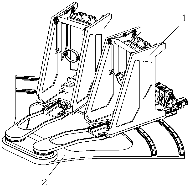
[0044] See figure 1 , A cord-driven horizontal lower limb rehabilitation robot includes a pair of foot fixing mechanism 1 and a support mechanism 2.

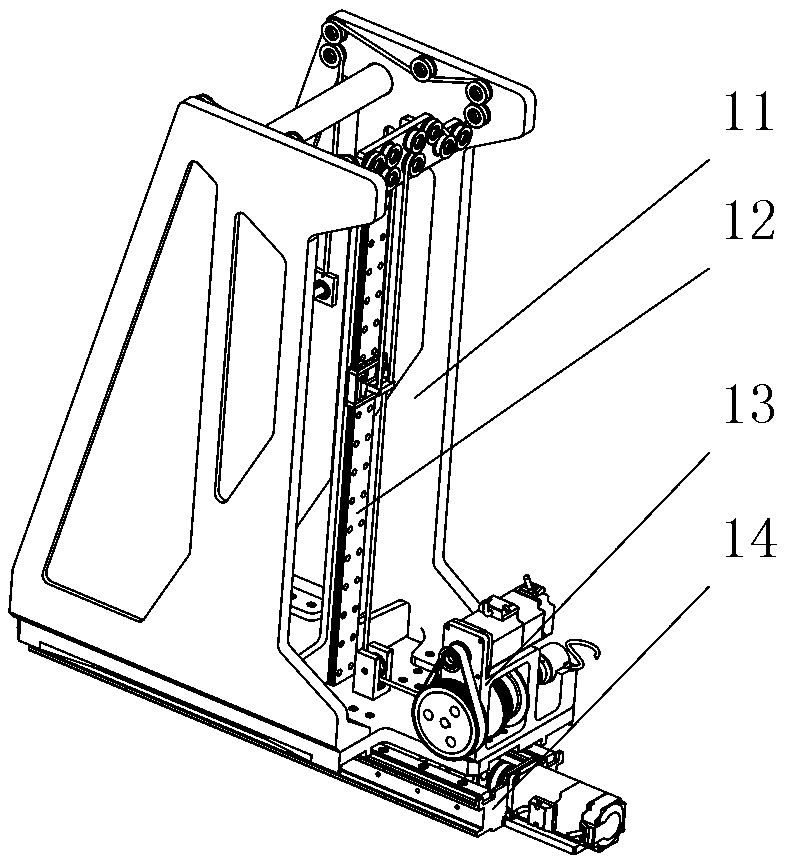
[0045] See figure 2 with image 3 , The foot fixing mechanism 1 includes a foot frame 11, a flexible cable guide mechanism 12, a vertical drive mechanism 13, a horizontal drive mechanism 14 and an ankle placement mechanism 15.

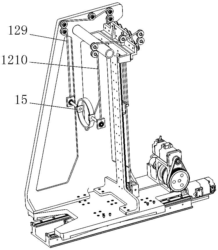
[0046] See Figure 4 , The foot frame 11 includes a bottom plate 111, a pair of side plates 113 and an I-shaped bracket 112; a pair of side plates 113 are fixedly installed on the bottom plate 111 in parallel and upright, and the I-shaped bracket 112 is installed between the pair of side plates 113 The middle of the bottom plate 111; the front of the I-shaped bracket 112 corresponds to the front of the bottom plate 111, and the back of the I-shaped bracket 112 corresponds to the rear of the bottom plate 111. A cross bar 115 and a tensioner bracket 114 are fixedly installed between the upper parts of the pair...


PUM


Abstract

The invention relates to a wire-driven horizontal lower limb rehabilitation robot, and belongs to medical equipment for assisting lower limb rehabilitation by robots. The wire-driven horizontal lowerlimb rehabilitation robot comprises a pair of foot fixing mechanisms and a support mechanism; each foot fixing mechanism comprises a foot rack, a wire guiding mechanism, a vertical driving mechanism,a horizontal driving mechanism and an ankle-containing mechanism; the horizontal driving mechanisms drive the pair of foot fixing mechanisms to slide back and forth relative to the support mechanism;and the vertical driving mechanisms control vertical movement in leg lifting rehabilitation exercise through the wire guiding mechanisms and the ankle-containing mechanisms. The freedom degree in thefront-back direction is innovatively introduced, wire driving is adopted, and lifting exercise cooperates with front-back compensation exercise in leg lifting rehabilitation training exercise to wellsimulate the leg lifting exercise; and the opening and closing auxiliary freedom degree of the two legs is increased, and the flexible lower limb rehabilitation exercise process can be well completed,so the good rehabilitation treatment effect is achieved. The robot is reasonable in structural design, convenient to disassemble and assemble and low in manufacturing cost.

Description

Technical field [0001] The invention belongs to the technical field of robots, and in particular relates to a robot-assisted medical equipment for lower limb rehabilitation; it is applied to lower limb rehabilitation robots to perform rehabilitation training, and more particularly relates to a robot-assisted device based on a flexible cable drive method and having two degrees of freedom. It is a cord-driven horizontal lower limb rehabilitation robot and rehabilitation training method. Background technique [0002] Before robots were used in the field of medical rehabilitation, paralyzed patients could only use traditional rehabilitation methods for rehabilitation training, that is, rehabilitation training could only be carried out through the full care and face-to-face guidance of rehabilitation physicians and nurses. This requires a large number of rehabilitation medical practitioners and nurses, but in fact the number of rehabilitation medical practitioners and nurses cannot ma...

Claims


Application Information

Patent Timeline
Patent Type & Authority Applications(China)
IPC IPC(8): A61H1/02
CPCA61H1/0237A61H2201/1215A61H2201/1481A61H2201/1642
Inventor 王正雨刘光明訾斌钱钧王道明钱森陈兵
Owner HEFEI UNIV OF TECH
Why Eureka
Try Eureka