Eureka AIR delivers breakthrough ideas for toughest innovation challenges, trusted by R&D personnel around the world.

Automatic welding machine

An automatic welding machine and laser welding technology, applied in welding equipment, laser welding equipment, other manufacturing equipment/tools, etc., can solve problems such as low stability and reliability, poor product processing quality, and reduced product competitiveness, and achieve The effect of high stability and reliability, high processing accuracy, and easy production control

Pending Publication Date: 2020-04-24
SUZHOU LINGYU ELECTRONICS TECH CO LTD
View PDF0 Cites 2 Cited by
  • Summary
  • Abstract
  • Description
  • Claims
  • Application Information

AI Technical Summary

Problems solved by technology

[0003] At present, during the processing of many stamping products, each part is usually processed separately and then welded together, such as some parts of 3C electronic products (the abbreviation of Computer, Communication and ConsumerElectronic), etc. However, the traditional manual process The corresponding tool welding method takes up a lot of manpower, takes a long time, is labor-intensive, inconvenient to operate, easily causes product pollution and other defects, poor product processing quality, low stability and reliability, and is not conducive to production control, especially For smaller products, products with complex shapes, etc., the production efficiency is low, the production cost is high, and the competitiveness of the product is reduced

Method used


Image

  • Automatic welding machine
  • Automatic welding machine
  • Automatic welding machine

Examples


Embodiment

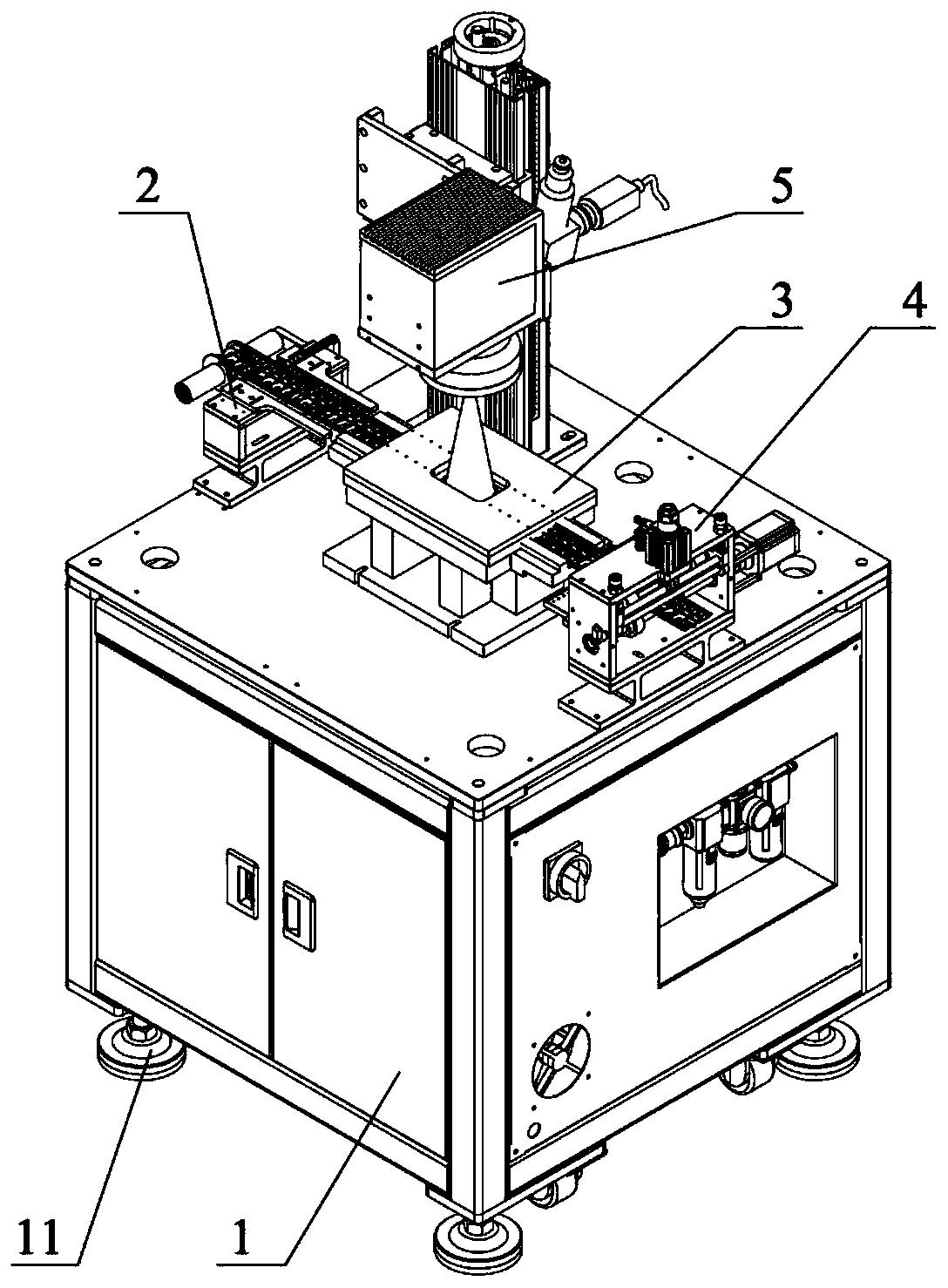
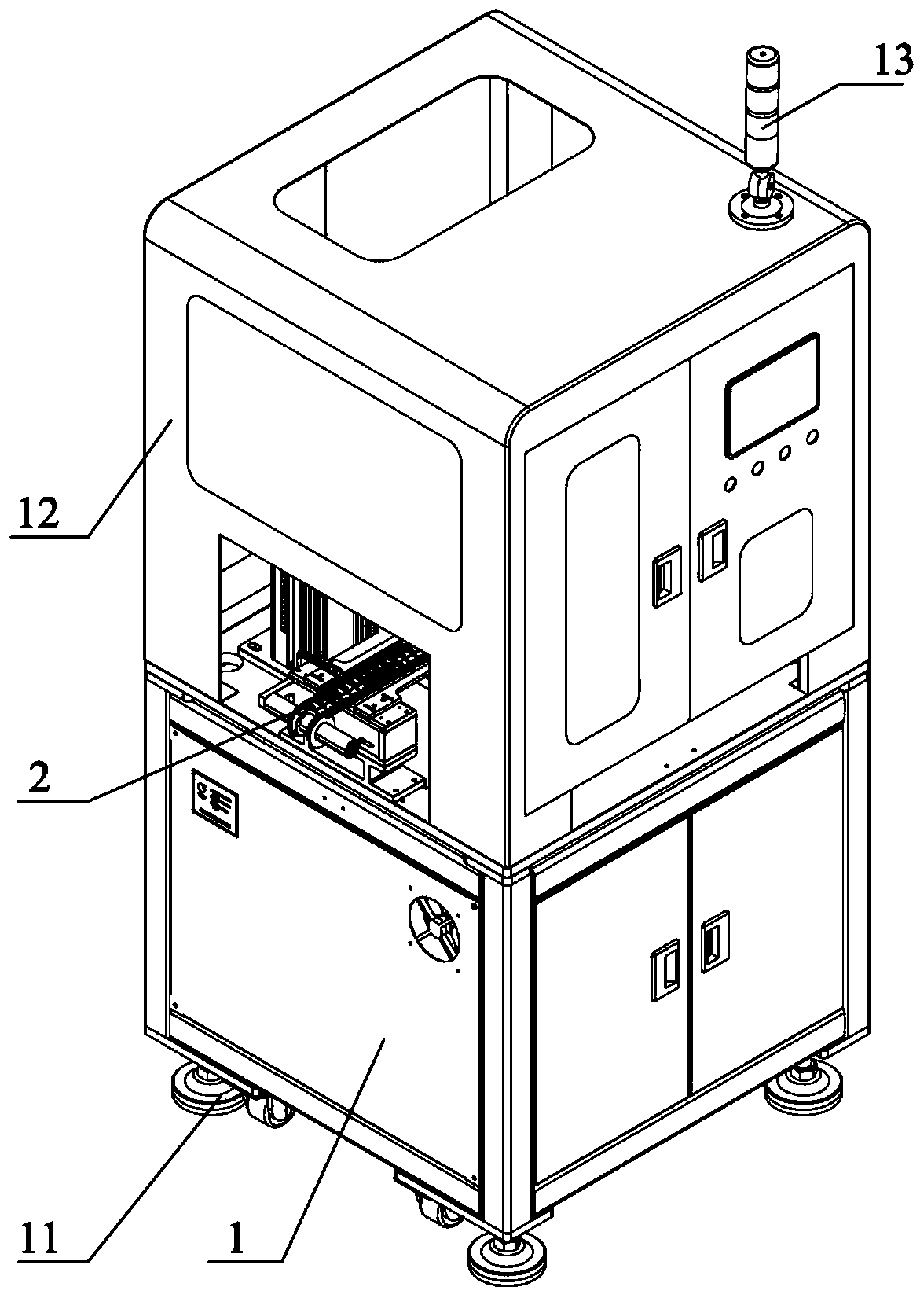
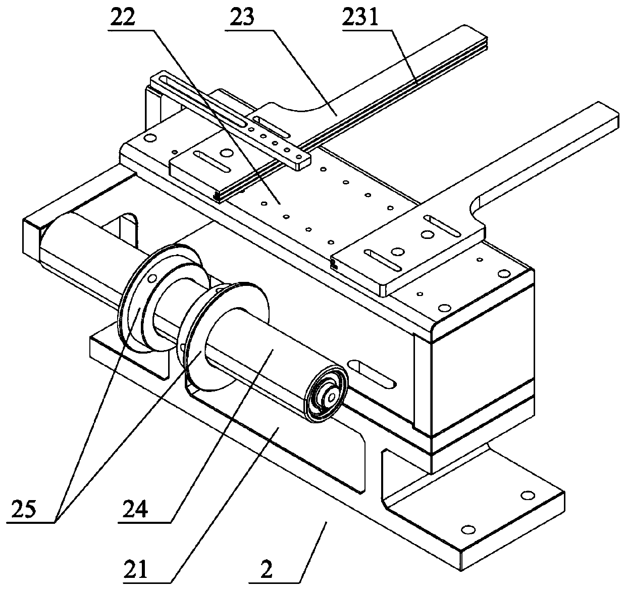
[0033] Such as Figure 1-8As shown, an automatic welding machine includes a frame 1, and the top of the frame 1 is usually provided with a working base plate. A laser welding device 5 is arranged above the device 3, and a first avoidance hole 301 corresponding to the laser welding device 5 is arranged on the stamping device 3, and the material pulling device 4 can pull the strip through the straightening device 2 and the stamping device 3 in turn. And the material pulling device 4, when the product processed and formed on the material belt is located in the first avoidance hole 301 on the punching device 3, the material pulling device 4 stops pulling the material, and the punching device 3 first positions and compresses the material belt passing through it, Then the laser welding device 5 above the stamping device 3 welds the product on the material strip in the first avoidance hole 301, and then the stamping device 3 cuts off the redundant connecting material point of the pro...


PUM


Abstract

The invention provides an automatic welding machine. The automatic welding machine comprises a rack, wherein a guiding device, a stamping device and a material pulling device are sequentially arrangedon the rack, a laser welding device is arranged above the stamping device, a first receding hole corresponding to the laser welding device is formed in the stamping device, the material pulling device can pull a material belt to sequentially penetrate through the guiding device, the stamping device and the material pulling device, the laser welding device can weld a product located in the first receding hole and on the material belt, the stamping device can position and press the material belt penetrating through the stamping device, and can cut off redundant material connecting points of thewelded product. According to the automatic welding machine, automatic welding machining of the product is achieved, operation is easy and convenient, the product machining precision is high, the quality is good, manpower and time are effectively saved, the production efficiency is improved, stability and reliability are high, production management and control are convenient, and the production cost is reduced.

Description

technical field [0001] The present disclosure relates to the technical field of welding equipment, in particular to an automatic welding machine. Background technique [0002] With the continuous progress of society and the rapid development of science and technology, the market demand for many products is increasing, and the requirements are also getting higher and higher. Therefore, it is necessary to ensure product quality and improve production efficiency to meet market demand. Stamping is a forming processing method that applies external force to plates, strips, pipes and profiles by presses and molds to cause plastic deformation or separation to obtain stamped parts of required shape and size. Compared with castings and forgings, stamping parts have the characteristics of thinness, uniformity, lightness and strength. They also have high processing efficiency, can realize complex size processing, simple operation, high strength, stable quality and good performance. They...

Claims


Application Information

Patent Timeline
Patent Type & Authority Applications(China)
IPC IPC(8): B23P23/06B23K26/00B23K26/60B23K26/70
CPCB23P23/06B23K26/0093B23K26/60B23K26/702
Inventor 于润泽韦斌
Owner SUZHOU LINGYU ELECTRONICS TECH CO LTD
Why Eureka
Eureka Blog
Learn More