
Chain tensioning device with adjustable tensioning force

A chain tensioning device, tensioning force technology, applied in the field of garbage storage devices

Active Publication Date: 2020-04-24
重庆众思创智能科技有限公司
View PDF6 Cites 2 Cited by
  • Summary
  • Abstract
  • Description
  • Claims
  • Application Information

AI Technical Summary

Problems solved by technology

[0005] The present invention intends to provide a chain tensioning device with adjustable tension to solve the problem that the chain tensioning device in the prior art cannot continuously and stably provide stable tension to the chain

Method used


Image

  • Chain tensioning device with adjustable tensioning force
  • Chain tensioning device with adjustable tensioning force
  • Chain tensioning device with adjustable tensioning force

Examples


Embodiment 1

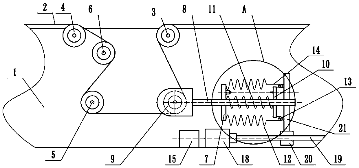
[0036] Embodiment one is basically as figure 1 with figure 2 As shown, a chain tensioning device with adjustable tension force includes a base 1, on which a transmission chain 2 is arranged, and on the base 1, a drive wheel 3 and a driven wheel 4 are fixedly connected by screws. Wheel 5 and buffer wheel 6, chain 2 and drive wheel 3, steering wheel 5, buffer wheel 6 and driven wheel 4 are meshed successively and carry out transmission.

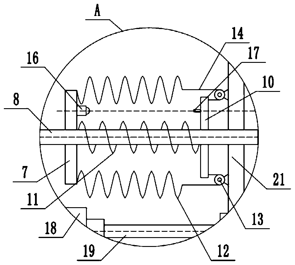
[0037] Such as figure 1 As shown, the base 1 is fixedly connected with a support seat 7 by screws, and the support seat 7 is provided with a guide hole arranged horizontally, and a slide bar 8 is connected to slide horizontally in the guide hole. Tightening pulley 9, the tensioning pulley 9 meshes with the inner side of the chain 2 and the tensioning pulley 9 is located between the driving pulley 3 and the steering wheel 5, the tensioning pulley 9 and the steering pulley 5 are located in the same horizontal plane, and the right end of the sl...

Embodiment 2

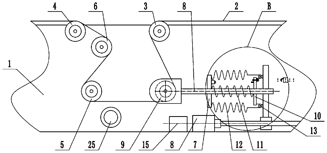
[0045] The difference between embodiment two and embodiment one is: as image 3 with Figure 4As shown, the support base 7 is provided with a detection mechanism for detecting the elongation of the chain 2, and the detection mechanism is provided with an alarm unit. In this embodiment, the detection mechanism includes a travel switch 22 and a trigger lever 23 for triggering the travel switch 22. , the alarm unit includes an alarm 25 and a power supply (not shown in the figure). Two horizontally arranged lockholes can be locked into different lockholes by the travel switch 22, so that the distance between the travel switch 22 and the trigger lever 23 is adjustable; the travel switch 22 is electrically connected with the alarm 25 and the power supply, and the stroke When the switch 22 was closed, the alarm 25 was energized and sent an alarm; the push pedal 10 had a through hole, and the trigger rod 23 was inserted into the through hole, and the left end of the trigger rod 23 pr...


PUM


Abstract

The invention relates to the technical field of garbage storing devices, in particular to a chain tensioning device with the adjustable tensioning force. The chain tensioning device with the adjustable tensioning force comprises a base and a supporting base fixedly connected to the base; a sliding rod is slidably connected to the supporting base, a tensioning wheel meshing with a chain is fixedlyconnected to one end of the sliding rod, a pushing plate is fixedly connected to the other end of the sliding rod, the sliding rod is provided with a first elastic part, and the first elastic part islocated between the supporting base and the pushing plate; and a compensation mechanism used for conducting tension compensation on the sliding rod is connected between the supporting base and the pushing plate, and the tensioning force of the sliding rod on the tensioning wheel is kept invariable under the combined action of the elastic force of the first elastic part and the compensated tensioning force of the compensation mechanism. According to the chain tensioning device with the adjustable tensioning force, the elastic force reduction of the first elastic part is compensated through thecompensation mechanism, therefore, the tensioning force borne by the chain in the using process is always kept invariable, and the problem that in the prior art, a chain tensioning device cannot continuously and stably supply stable tensioning force to the chain is solved.

Description

technical field [0001] The invention relates to the technical field of garbage storage devices, in particular to a chain tensioning device with adjustable tension force. Background technique [0002] Power-free conveyor is a kind of transportation equipment suitable for high productivity and flexible production system. It not only plays the role of transportation, but also runs through the entire production line, integrating excellent process operation, storage and transportation functions. With the rapid development of modern logistics transportation technology, positive and free conveyors are widely used in all walks of life, especially in the automobile manufacturing industry, four-door assembly lines, engine assembly lines, vehicle assembly lines, etc. are widely used. The power free conveyor mainly relies on the chain to complete the power transmission. The conveying trolley used to transmit the workpiece is equipped with a sprocket meshing with the chain, so that the c...

Claims


Application Information

Patent Timeline
Patent Type & Authority Applications(China)
IPC IPC(8): B65G23/44
CPCB65G23/44
Inventor 覃忠华杨斌
Owner 重庆众思创智能科技有限公司
Learn More