Anti-pulling device and seismic isolation protection method

A technology of anti-drawing and seismic isolation, which is applied in the direction of protective buildings/shelters, earthquake-proof, building components, etc., can solve the problems of reducing tensile stress and easy tensile failure, so as to reduce tensile stress and tensile action area Large, the effect of improving the effectiveness of seismic isolation

Active Publication Date: 2020-04-24
ZHUZHOU TIMES NEW MATERIALS TECH
View PDF11 Cites 0 Cited by
  • Summary
  • Abstract
  • Description
  • Claims
  • Application Information

AI Technical Summary

Problems solved by technology

[0014] The anti-drawing device and shock isolation protection method provided by the present invention realize the horizontal multi-directional sliding of the tensile plate assembly relative to the rotating assembly, and the anti-drawing device is used together with the shock-isolation device, and the shock-isolation device produces large and multi-directional The pull-out device can produce synchronous horizontal movement with the seismic isolation device during the horizontal inter-story displacement, and can still provide a large enough tensile bearing capacity when the horizontal inter-story displacement is large, thereby reducing the tensile stress on the seismic isolation device. Protect the seismic isolation device from tensile stress damage, solve the problem that the seismic isolation device is prone to tensile failure under large horizontal displacement, and provide effective tensile protection for the seismic isolation device under strong earthquake conditions, improve the effectiveness of seismic isolation and prevent the occurrence of superstructure overturned

Method used


Image

  • Anti-pulling device and seismic isolation protection method
  • Anti-pulling device and seismic isolation protection method
  • Anti-pulling device and seismic isolation protection method

Examples


Embodiment Construction

[0034] Combine below Figure 1 to Figure 3 Embodiments of the present invention are described in detail.

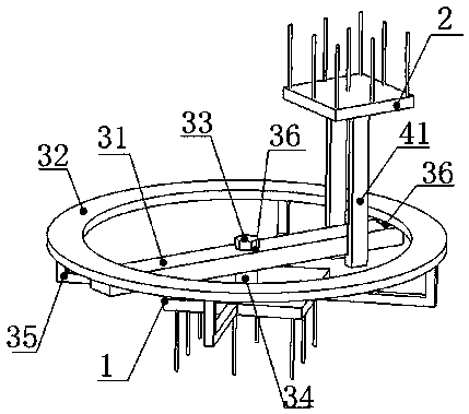
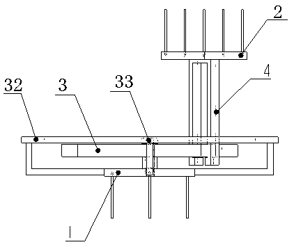
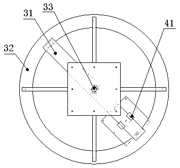
[0035] The anti-pullout device is installed between the base structure and the superstructure, including a base 1 fixed to the base structure and a top plate 2 fixed to the superstructure and located above the base 1, characterized in that the base 1 is equipped with horizontal and The rotatable rotating assembly 3, the top plate 2 is equipped with a vertical tensile plate assembly 4, the tensile plate assembly 4 is movably connected with the rotating assembly 3, and the upward pulling force of the top plate 2 is transmitted to the base 1, and the rotating assembly 3 follows The horizontal movement of the tensile plate assembly 4 rotates to adapt to the change of the horizontal movement direction of the tensile plate assembly 4 .

[0036] The above-mentioned anti-drawing device is connected between the base 1 and the top plate 2 with the tensile plate assembly 4 and the ...


PUM


Abstract

The anti-pulling device is installed between a foundation structure and an upper-layer structure, comprises a base fixed to the foundation structure and a top plate fixed to the upper-layer structureand located above the base, and is characterized in that a horizontally-arranged and rotatable rotating assembly is installed on the base, a vertically-arranged anti-pulling plate assembly is installed on the top plate, the anti-pulling plate assembly is movably connected with the rotating assembly, upward pulling force of the top plate is transmitted to the base, and the rotating assembly rotatesalong with horizontal movement of the anti-pulling plate assembly to adapt to the change in the horizontal movement direction of the anti-pulling plate assembly. The anti-pulling device can generatesynchronous and horizontal movement with a seismic isolation device, and can still provide enough anti-pulling bearing capacity when the displacement between horizontal layers is large, so that the pulling stress borne by the seismic isolation device is reduced, the seismic isolation device is protected against being damaged by the pulling stress, the seismic isolation device is effectively protected against tension under a strong seismic state, and the seismic isolation effectiveness is improved to prevent the upper-layer structure from overturning. A seismic isolation protection method is further provided.

Description

technical field [0001] The invention relates to an anti-drawing device and a shock-isolation protection method, belonging to the technical field of shock-isolation and anti-drawing. Background technique [0002] Seismic isolation technology is more and more widely used in high-intensity areas. The structural system of buildings is becoming more and more complex and the volume is increasing. Adding a seismic isolation layer at the lower part of the structure can effectively prolong the natural vibration period and overall damping of the structure. The seismic isolation device It can dissipate a large amount of ground vibration input energy. For isolation structures in high-seismic intensity areas, especially higher-rise isolation structures and large-scale isolation structures, in order to achieve a better isolation effect, reducing the horizontal stiffness of the isolation layer often leads to excessive displacement of the isolation layer and The pull-out problem of the sei...

Claims


Application Information

Patent Timeline
IPC IPC(8): E04B1/98E04H9/02
CPCE04B1/98E04H9/023
Inventor 陈国平冷新云庾光忠罗勇欢姜良广周函宇
Owner ZHUZHOU TIMES NEW MATERIALS TECH
Why Eureka
Try Eureka