Design method, support structure and construction method of gob-side entry retaining support structure

A support structure and design method technology, applied in mining equipment, earth square drilling, ceramic products, etc., can solve problems such as collapse damage, filling wall structure instability, difficulty in ensuring the connection density of material junctions, etc., to ensure Integrity, reducing the risk of gas accumulation, and the effect of preventing dynamic pressure shock disasters

Active Publication Date: 2021-06-01
SHANDONG UNIV
View PDF5 Cites 0 Cited by
  • Summary
  • Abstract
  • Description
  • Claims
  • Application Information

AI Technical Summary

Problems solved by technology

However, the inventors found that this roadside filling method uses two materials with different properties to construct the roadside filling wall, and it is difficult to ensure the compactness of the connection at the junction of the two materials, so it is easy to be filled under the action of horizontal side pressure. The relative displacement between the flexible filling material and the rigid filling material will lead to the instability of the filling wall structure, collapse and damage

Method used


Image

  • Design method, support structure and construction method of gob-side entry retaining support structure
  • Design method, support structure and construction method of gob-side entry retaining support structure
  • Design method, support structure and construction method of gob-side entry retaining support structure

Examples


Embodiment 2

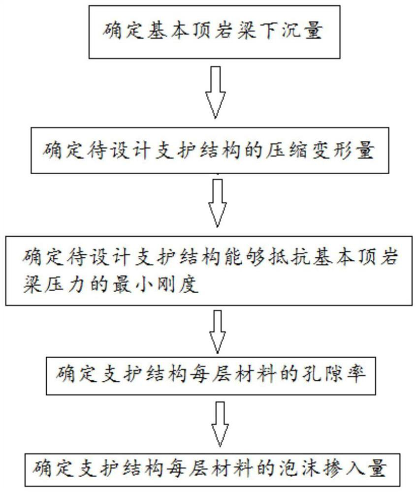
[0113] This embodiment discloses a gob-side retaining structure, which is designed using the design method described in Embodiment 1, and is formed by pouring fiber-reinforced foam concrete layer by layer, and the amount of foam to be mixed in each layer is based on the design method to obtain.

Embodiment 3

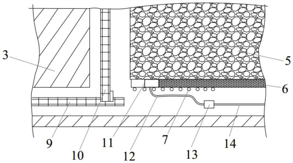
[0115] This embodiment discloses a construction method for the side support structure of gob-side entry retaining, such as Figure 2-4 shown, including the following steps:

[0116] Step 1: Arranging a plurality of hydraulic props 7 in the roadway, the top surface of the hydraulic props is in contact with the direct roof and the bottom surface to support the direct roof and the basic roof.

[0117] The hydraulic prop adopts a hydraulic jack, and its arrangement direction is perpendicular to the working face of the coal wall, and is located on the gangue side.

[0118] Step 2: pouring the gob-side retaining structure with fiber-reinforced foam concrete at the position between the gangue and the hydraulic prop.

[0119] Specifically, the preparation of fiber-reinforced foamed concrete is carried out on the ground. The preparation method is: 45# cement, fly ash and gypsum are mixed according to a set ratio to form a dry mix, and then mixed with polypropylene fibers to form a pow...


PUM

PropertyMeasurementUnit
thicknessaaaaaaaaaa
thicknessaaaaaaaaaa
densityaaaaaaaaaa

Abstract

The invention relates to a design method, a support structure and a construction method for a gob-side retaining structure, comprising the following steps: step 1: determine the rock beam sinking amount of the basic roof on one side of the working face; step 2: determine the support to be designed compression deformation of the support structure; step 3: calculate the minimum stiffness of the support structure to be designed to resist the pressure of the basic top rock beam according to the obtained pressure; step 4: inversely deduce the value of the support structure to be designed according to the stiffness obtained in step 3 The porosity of the constituent materials; Step 5: Divide the support structure to be designed into multi-layers with gradient changes in porosity from bottom to top, and obtain the minimum porosity of the bottom material of the support structure and the maximum porosity of the top material , and then obtain the porosity of each layer of material of the support structure; Step 6: calculate the foam incorporation of each layer of material when pouring according to the porosity of each layer of material of the support structure, use the support structure obtained by the design method of the present invention to have The function of allowing pressure to absorb energy, and the structure is stable.

Description

technical field [0001] The invention relates to the technical field of roadside support for gob-side entry retention, in particular to a design method, a support structure and a construction method for gob-side entry retention. Background technique [0002] As a pillarless mining technology, gobside entry retention is widely used in coal mine production. By retaining the transport roadway in the previous section of the working face as the return airway of the next section of the working face, retaining the gob-side entry can reduce the amount of roadway development, ease the tension of mining replacement, reduce the risk of gas accumulation in the corner of the working face, and improve the work efficiency. surface recovery rate. The support of gob-side retaining can be divided into roadway support and roadside support: roadway support mainly uses traditional bolts and other support methods to enhance the integrity of surrounding rock; the main function of roadside support ...

Claims


Application Information

Patent Timeline
Patent Type & Authority Patents(China)
IPC IPC(8): E21F15/04E21F15/00C04B28/14C04B38/10C04B111/40
CPCC04B16/0633C04B28/14C04B38/106C04B2111/40E21F15/005E21F15/04C04B7/02C04B18/08
Inventor 李利平商成顺孙子正屠文锋王利戈陈雨雪刘聪
Owner SHANDONG UNIV
Why Eureka
Try Eureka