Visual detection system for evaporator frosting and detection method thereof

A visual detection and detection method technology, applied in defrosting, damage protection, household appliances, etc., can solve problems such as easy fog, high cost, waste of energy, etc., to eliminate the impact of detection results, reduce the demand for quantity, reduce Effect of hardware cost

Pending Publication Date: 2020-04-24
NANJING INST OF TECH
View PDF0 Cites 14 Cited by
  • Summary
  • Abstract
  • Description
  • Claims
  • Application Information

AI Technical Summary

Problems solved by technology

However, due to various influencing factors in the complex and changeable actual environment, none of these methods can accurately judge the appropriate defrosting time. Often, when the degree of frosting is not high, the heating wire starts to work for defrosting, or When there is severe frost, but the defrosting has not yet started
This will not only affect the normal operation of the refrigeration equipment, affect the cooling efficiency, but also waste energy
[0004] As a means to directly detect the frosting on the surface of the evaporator, visual inspection technology can solve the problems of the above indirect measurement technology, so that it can accurately and reliably detect the appropriate defrosting time; however, after actual testing, it is found that , the visual system needs a relatively stable and uniform lighting condition when collecting images, and the camera is easily disturbed by the external environment. In addition, there is also the problem of limited shooting range of a single camera. When in use, the installation space of the evaporator is often very narrow and limited, which makes it difficult for the camera to collect images in a larger range. In order to collect a panoramic view of the evaporator Image needs to arrange dozens of cameras, the cost is too high

Method used


Image

  • Visual detection system for evaporator frosting and detection method thereof
  • Visual detection system for evaporator frosting and detection method thereof
  • Visual detection system for evaporator frosting and detection method thereof

Examples


Embodiment Construction

[0064] The technical scheme of the present invention will be further described in detail below in conjunction with the accompanying drawings:

[0065] The technical solutions in the embodiments of the present invention will be clearly and completely described below in conjunction with the accompanying drawings in the embodiments of the present invention. Obviously, the described embodiments are only a part of the embodiments of the present invention, rather than all the embodiments. Based on the embodiments of the present invention, all other embodiments obtained by those of ordinary skill in the art without creative work shall fall within the protection scope of the present invention

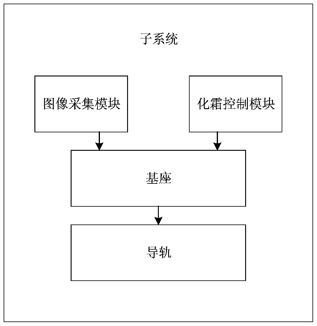
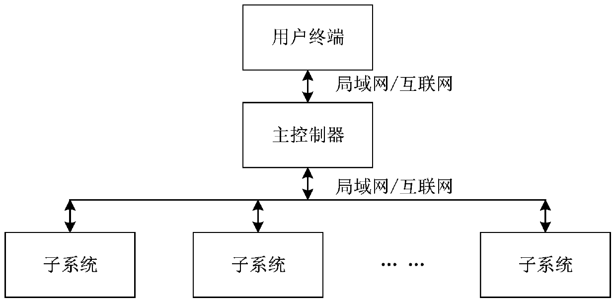
[0066] The present invention designs a visual detection system for evaporator frosting. The detection system can be divided into three parts: subsystems, main controllers, and terminals. Each part communicates through a local area network and the Internet.

[0067] As attached figure 1 As shown, the s...


PUM


Abstract

The invention discloses a visual detection system for evaporator frosting and a detection method thereof, and relates to the technical field of evaporator frosting condition detection. The method comprises the following specific steps that through movement of an image acquisition device on a guide rail, frosting image sets on the back faces of multiple evaporators can be acquired through one camera, the image sets are converted into panoramic images through the image splicing and fusion technology, through the identification of the mark points arranged on the back surface of the evaporator, to-be-detected areas are segmented from the panoramic image, preprocessing and binarization are carried out on the target area, the frosting area percentage value can be calculated, the frosting degreeof the back face of the evaporator can be accurately reflected, and can be used as a basis for judging whether defrosting or refrigerating is performed, the aim of timely and accurately defrosting canbe achieved, and the refrigerating efficiency of the evaporator is provided, so that the energy consumption is reduced, and the cost is saved.

Description

Technical field [0001] The invention relates to the technical field of evaporator frosting condition detection, in particular to an evaporator frosting visual detection system and a detection method thereof. Background technique [0002] In the current refrigeration industry, evaporators are commonly used in the industry for refrigeration; during the refrigeration process, the surface of the evaporator will gradually form frost. When the degree of frost formation is severe, it will greatly reduce the refrigeration efficiency and cause energy waste, so it is necessary Defrost the evaporator. [0003] At present, the industry generally adopts the method of pre-determining the defrost time based on experience; there is also a method of indirectly detecting the degree of frost based on temperature detection and wind pressure detection to determine the timing of defrosting. However, due to the complex and changeable actual environment and various influencing factors, none of these meth...

Claims


Application Information

Patent Timeline
Patent Type & Authority Applications(China)
IPC IPC(8): F25D21/02F25D29/00F25B49/00F25B47/02
CPCF25B47/02F25B49/00F25D21/002F25D21/02
Inventor 黄家才邹俊陈田丁凌
Owner NANJING INST OF TECH
Why Eureka
Try Eureka