Acoustic emission sensor fixing device and using method thereof

A technology of acoustic emission sensor and fixing device, which is applied in the direction of material analysis using acoustic emission technology, measuring devices, and material analysis using sound waves/ultrasonic waves/infrasonic waves, etc. To meet the needs of practical applications and other issues, to achieve the effect of simple structure and convenient use

Pending Publication Date: 2020-04-24
HOHAI UNIV
View PDF0 Cites 2 Cited by
  • Summary
  • Abstract
  • Description
  • Claims
  • Application Information

AI Technical Summary

Problems solved by technology

The traditional method is to use two fixing methods: tape wrapping or rubber band binding, but the former is easy to form an overall constraint on the acoustic emission sensor and the specimen, resulting in a "hoop effect", which affects the test results; Overturning occurs during the process, which makes it difficult to ensure the reliability of the contact between the sensor and the test piece
The existing acoustic emission sensor fixing devices mostly use Newton’s third law as the basic starting point in terms of force characteristics, and the sensor is attached to the surface of the test piece by using a spring to apply pressure in the direction of the sensor axis. However, it cannot overcome the lateral force. The load caused by axial force and acceleration makes its scope of application limited to static loading, and it is not applicable to dynamic loading; and in terms of structure, it can only meet the needs of small cubes and cylinders in the laboratory. It is suitable for larger-sized test pieces or heterogeneous structures, but cannot meet the needs of practical engineering applications
For hydraulic concrete structures, there are various structural forms, even special-shaped structures, and the body size is usually large, and dynamic loading tests are often required. The existing acoustic emission sensor fixtures, both in structural form and force characteristics Can't meet demand

Method used


Image

  • Acoustic emission sensor fixing device and using method thereof
  • Acoustic emission sensor fixing device and using method thereof
  • Acoustic emission sensor fixing device and using method thereof

Examples


Embodiment

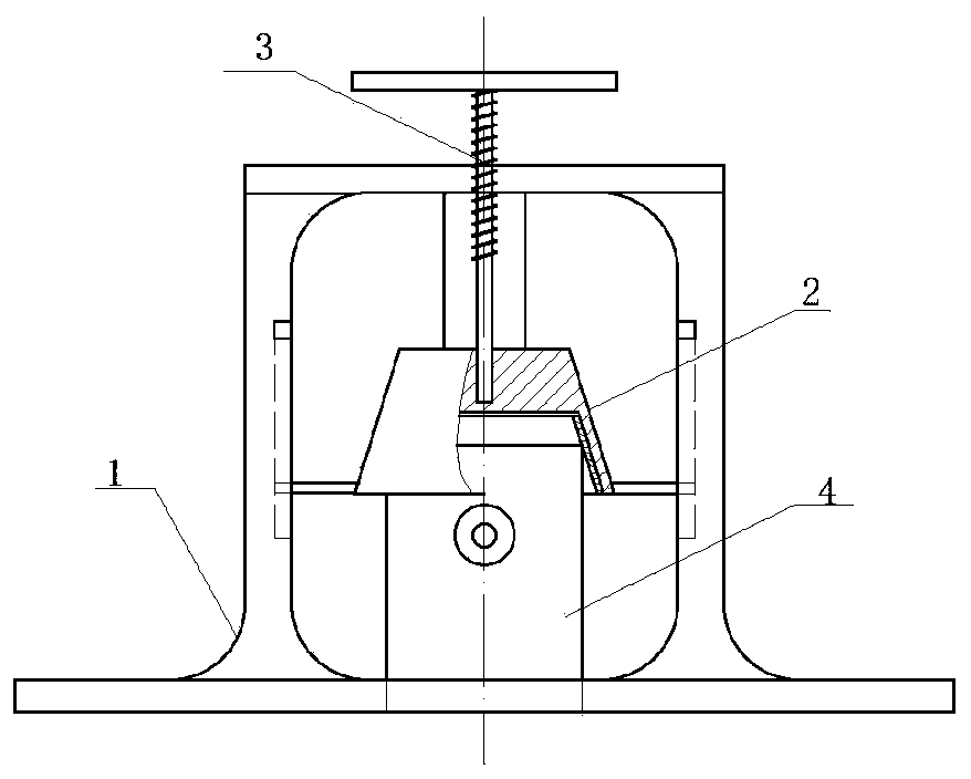
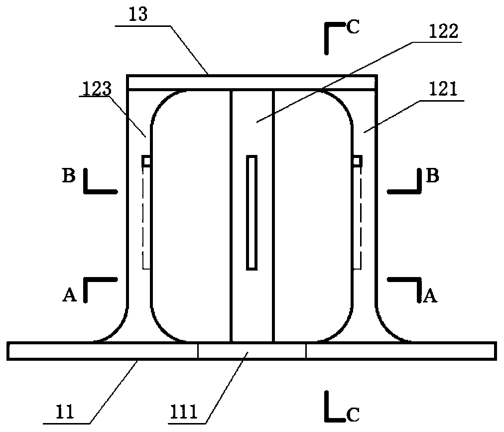
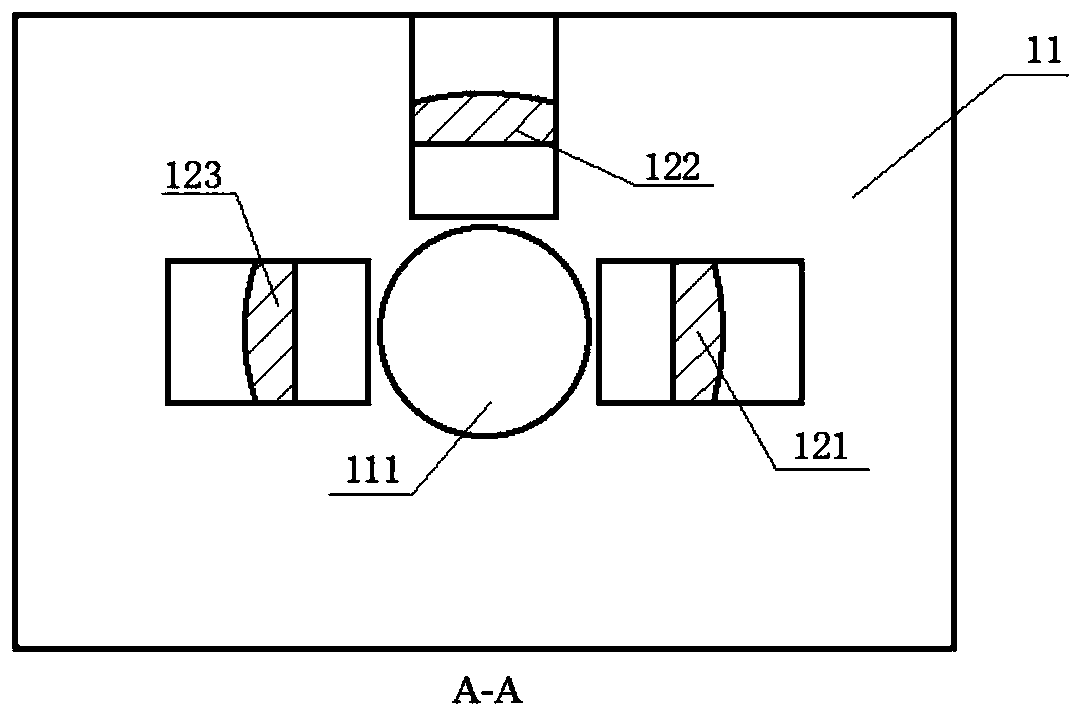
[0027] like Figure 1~5 As shown, the acoustic emission sensor fixing device includes a base frame 1, a gland 2, and an adjusting bolt 3. The adjusting bolt 3 passes through the top of the base frame 1 and is connected to the gland 2. The base frame 1 is provided with a mounting hole 111 for limiting the acoustic emission. The installation position of the sensor 4, the gland 2 is in the shape of a hollow circular platform, and the adjusting bolt 3 exerts force on the gland 2, so that the acoustic emission sensor 4 is closely attached to the surface of the test piece, and the gland 2 can position the acoustic emission sensor 4 in the circumferential direction. Restricted, the base frame 1 includes a base 11, a vertical plate 12 installed on the base 11 and a top plate 13 covered on the vertical plate 12, the base 11 is provided with a mounting hole 111 for fixing the acoustic emission sensor 4, and the vertical Plate 12 comprises right vertical plate 121, back vertical plate 12...


PUM

PropertyMeasurementUnit
particle diameteraaaaaaaaaa

Abstract

The invention discloses an acoustic emission sensor fixing device and a using method thereof. The device comprises a base frame, a gland and an adjusting bolt, wherein the adjusting bolt is connectedwith the gland, a mounting hole is formed in the base frame, the gland is in a hollow circular truncated cone shape, the adjusting bolt applies force to the gland, the acoustic emission sensor is tightly attached to the surface of a concrete structure, and the gland can limit the circumferential position of the acoustic emission sensor. The using method of the device comprises the following steps:(S1) the base frame is bonded to the surface of a concrete structure; (S2) the gland is pushed into the base frame; (S3) the acoustic emission sensor is placed in the mounting hole and the gland is pressed on the acoustic emission sensor; (S4) a force is applied to the gland by using the adjusting bolt; and (S5) the device and the sensor are recovered according to a process with an opposite installation sequence after the signal acquisition is finished. The device can provide stable circumferential clamping force for the acoustic emission sensor, and is suitable for tests of various loads andactual engineering measurement scenes; and the hoop effect is prevented from being generated to influence the test effect.

Description

technical field [0001] The present invention relates to a fixing device and a using method thereof, more particularly, to an acoustic emission sensor fixing device and a using method thereof. Background technique [0002] Acoustic emission technology, as a real-time dynamic monitoring technology, has been more and more used in the experimental research and practical engineering of civil structures. The reliability of the attachment of the sensor to the monitored object is crucial to the acquisition of acoustic emission data, which directly determines the effectiveness of monitoring. It is quite difficult to fix acoustic emission sensors on the surface of quasi-brittle artificial stone such as concrete. The traditional method is to use two fixing methods: tape wrapping or rubber band binding, but the former is easy to form an overall constraint on the acoustic emission sensor and the specimen, resulting in a "hoop effect", which affects the test results; Rollover occurs dur...

Claims


Application Information

Patent Timeline
Patent Type & Authority Applications(China)
IPC IPC(8): G01N29/14G01N29/22G01N3/06G01N3/02
CPCG01N3/02G01N3/06G01N29/14G01N29/22G01N2203/0658G01N2291/0232
Inventor 苏怀智周仁练
Owner HOHAI UNIV
Why Eureka
Try Eureka