
Design method suitable for winding of multistage capacitance-regulating transformer

A design method and transformer technology, applied in the direction of transformer/inductor coil/winding/connection, transformer/inductor parts, transformer, etc., can solve the problems of reducing the life of the transformer, increasing the cost, and damaging the transformer, so as to save materials Effect

Pending Publication Date: 2020-04-24
YUNNAN POWER GRID CO LTD KUNMING POWER SUPPLY BUREAU
View PDF3 Cites 0 Cited by
  • Summary
  • Abstract
  • Description
  • Claims
  • Application Information

AI Technical Summary

Problems solved by technology

The biggest and most essential difference from ordinary transformers is that the number of winding turns of capacity regulating transformers changes according to the load, and the operating conditions of windings are very different from ordinary transformers. If the optimal design is not carried out, not only will the transformer be damaged, but also reduce The life of the transformer will increase the cost and reduce the operating efficiency

Method used


Image

  • Design method suitable for winding of multistage capacitance-regulating transformer
  • Design method suitable for winding of multistage capacitance-regulating transformer
  • Design method suitable for winding of multistage capacitance-regulating transformer

Examples


Embodiment Construction

[0022] The following will clearly and completely describe the technical solutions in the embodiments of the present invention with reference to the accompanying drawings in the embodiments of the present invention. Obviously, the described embodiments are only some, not all, embodiments of the present invention. Based on the embodiments of the present invention, all other embodiments obtained by persons of ordinary skill in the art without making creative efforts belong to the protection scope of the present invention.

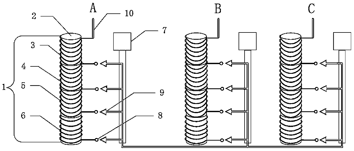
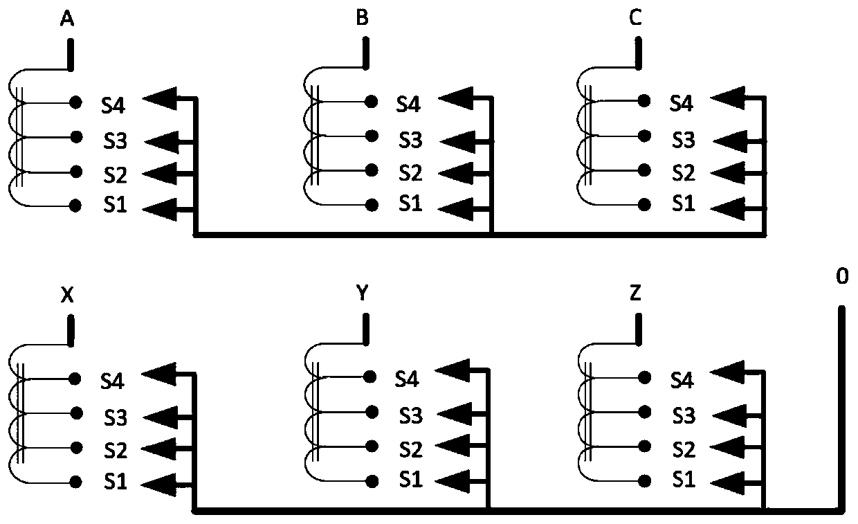
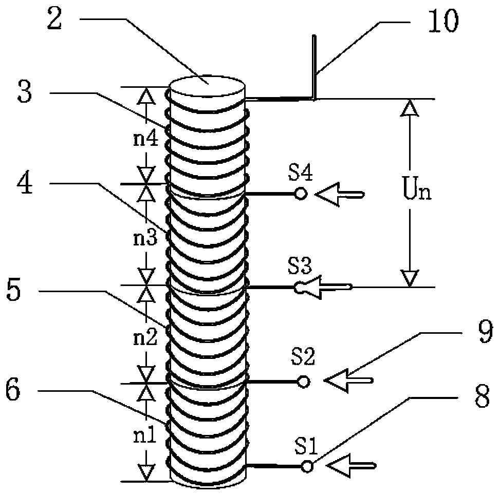
[0023] A design method for windings suitable for multi-stage capacity regulating transformers, the windings include iron core 2, section IV winding 3, section III winding 4, section II winding 5, section I winding 6, winding static contact 8, Winding lead wire 10, the structural diagram of the winding is as follows figure 1 shown; the method includes the following:

[0024] 1) The Section IV winding 3, Section III winding 4, Section II winding 5, and Section ...


PUM


Abstract

The invention discloses a design method suitable for a winding of a multistage capacity regulating transformer. The winding comprises an iron core, a fourth-section winding, a third-section winding, asecond-section winding, a first-section winding, winding static contacts and a winding leading-out line. The method comprises the following steps: (1) connecting the fourth-section winding, the third-section winding, the second-section winding and the first-section winding in series, winding the windings on the iron core, and wrapping the windings with an insulating material; 2) designing the wire diameters and insulation levels of the fourth-section winding, the third-section winding, the second-section winding and the first-section winding in a segmented manner under different transformer capacities according to the corresponding capacities, and matching with the winding current and turn voltage of each section under an actual capacity; and 3) changing the connection between a switch moving contact and the different static contacts of the winding through the action of a capacitance regulating switch to achieve the purpose of changing the number of turns of the winding between the winding leading-out wire and the switch moving contact. The method not only saves materials and reduces the loss of the transformer, but also ensures the operation efficiency and improves the power supply reliability.

Description

technical field [0001] The invention relates to the technical field of transformers, in particular to a design method suitable for windings of multi-stage capacity regulating transformers. Background technique [0002] Transformer is an important power equipment in the process of power transmission, and it is responsible for the important mission of connecting the power grid and users in the distribution network. With the improvement of living standards, the power load continues to increase. The transformer will be overloaded and heavily overloaded during the peak of power consumption, which will reduce the operating efficiency of the transformer and damage the transformer. Light load will appear during the valley of power consumption, increasing the no-load damage. The mismatch between the capacity of the distribution transformer and the load is becoming more and more prominent. The capacity of the transformer cannot be matched with the load in real time, which not only red...

Claims


Application Information

Patent Timeline
Patent Type & Authority Applications(China)
IPC IPC(8): H01F27/28H01F27/32H01F29/02
CPCH01F27/28H01F27/323H01F29/025
Inventor 陈治廷周浩然邱靖雯潘雅佳杨林鑫杜楠
Owner YUNNAN POWER GRID CO LTD KUNMING POWER SUPPLY BUREAU
Learn More