Supercharge Your Innovation With Domain-Expert AI Agents!

Electric connector and manufacturing method thereof

A technology of an electrical connector and a manufacturing method, applied in the direction of connection, elastic body connector, parts of the connecting device, etc., can solve the problems of deformation of the body, affecting the use of the electrical connector, and the electrical connector cannot guarantee the electrical connection, etc. Achieve the effect of not easy to deform and easy to assemble

Active Publication Date: 2020-04-24
DEYI PRECISION ELECTRONIC IND CO LTD PANYU
View PDF6 Cites 2 Cited by
  • Summary
  • Abstract
  • Description
  • Claims
  • Application Information

AI Technical Summary

Problems solved by technology

The above-mentioned fixing structure is convenient for mass production of conductive terminals, but this fixing structure often needs to interfere with the body during the use of the electrical connector to achieve holding the conductive terminals, for example, the thorns are stuck into the hole wall of the receiving hole. It is inevitable to apply a certain amount of stress to the body. If the electrical connector is provided with a large number of conductive terminals, this stress will be superimposed and magnified, resulting in deformation of the body, which in turn affects the use of the electrical connector, resulting in the electrical connector being unable to guarantee the connection with the mating components. stable electrical connection between

Method used


Image

  • Electric connector and manufacturing method thereof
  • Electric connector and manufacturing method thereof
  • Electric connector and manufacturing method thereof

Examples


no. 2 example

[0058] The manufacturing method of the second embodiment includes the following steps:

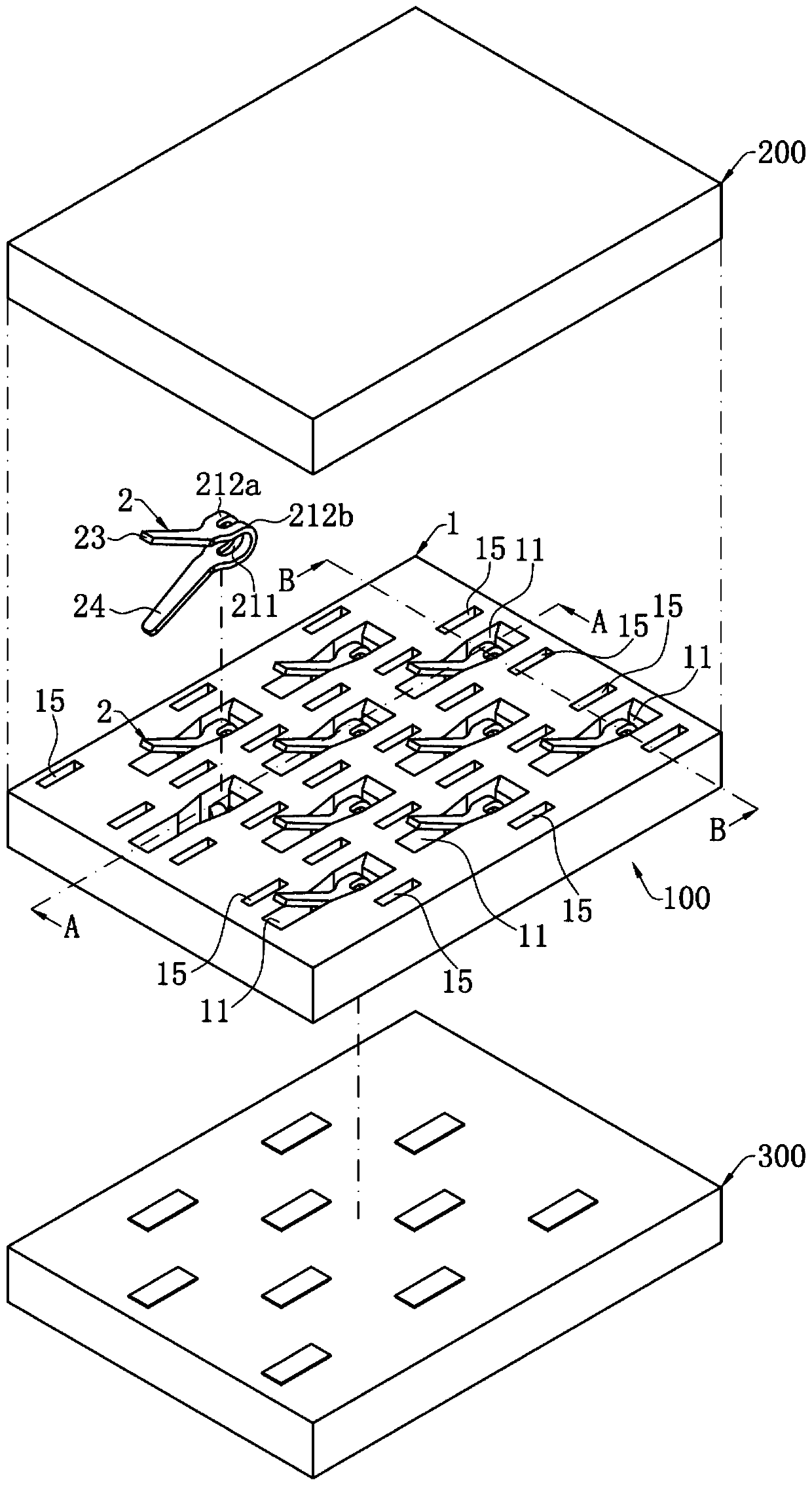
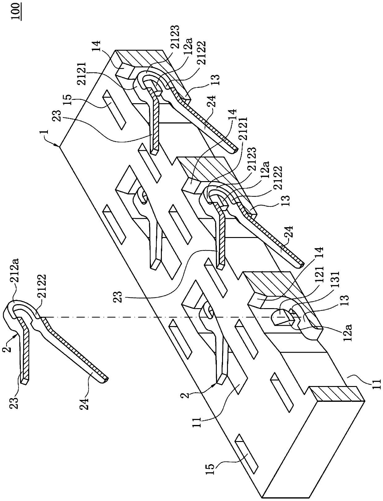
[0059] S1: if Figure 7 and Figure 8 As shown, the body 1 is provided, the lower edge of the first bump 12a and the lower edge of the second bump 12b (not shown) are arc-shaped, and a plurality of conductive terminals 2, each The upper elastic arm 23 of the conductive terminal 2 is connected to a material strip 400;

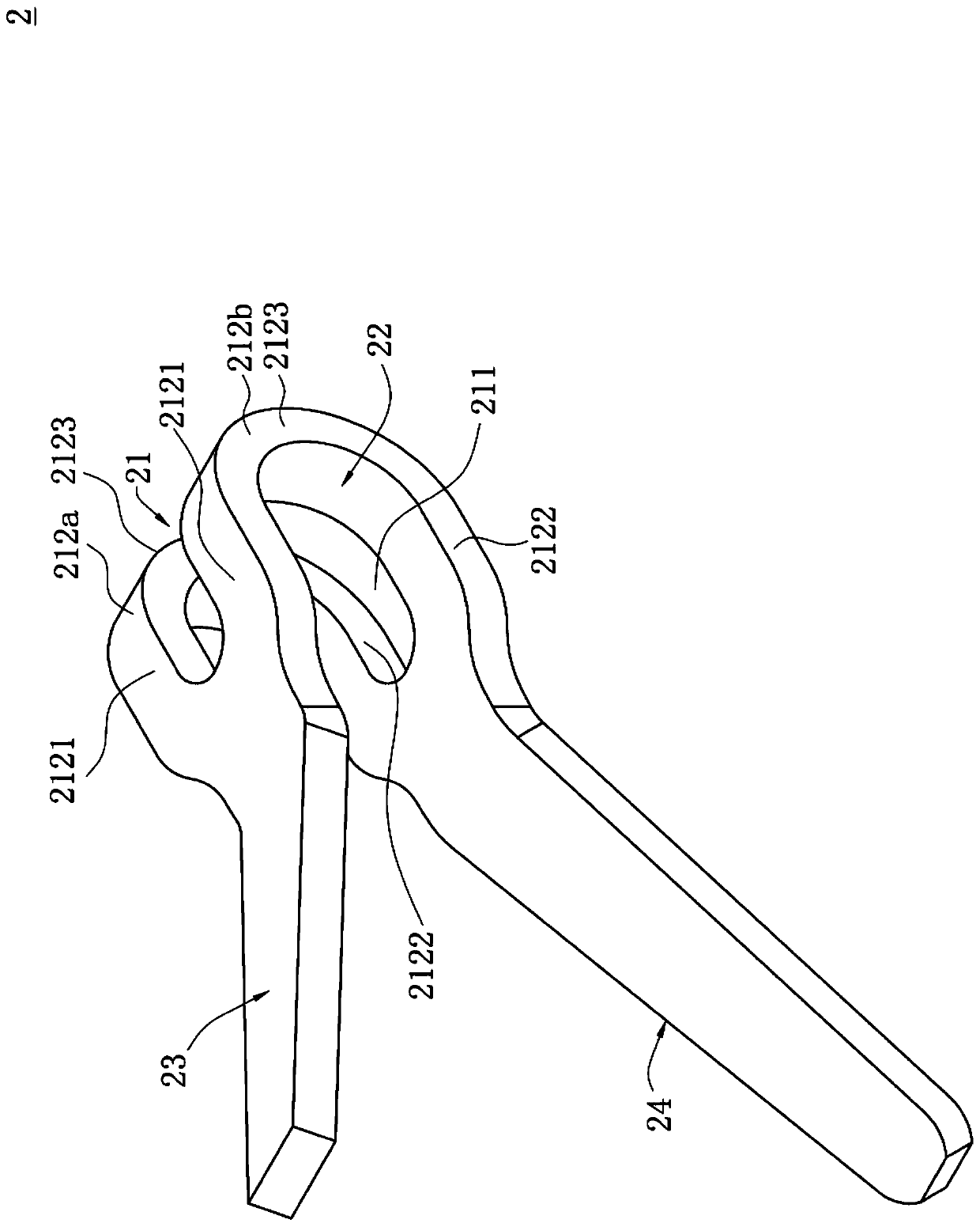
[0060] S2: if Figure 8 and Figure 9 As shown, the conductive terminal 2 whose receiving space 22 is opened upwards is inserted into the receiving hole 11 through the material strip 400, and the connecting section 2123 of the first branch 212a passes through the first protrusion downwards. block 12a, and is abutted by the first bump 12a, the connecting section 2123 of the second branch 212b passes down the second bump 12b, and is abutted by the second bump 12b connected, so that the first branch 212a and the second branch 212b are deformed closer to the through groove ...


PUM


Abstract

The invention discloses an electric connector and a manufacturing method thereof. The electric connector comprises a body with a containing hole, and the containing hole is provided with at least oneprotruding block in a protruding mode and a supporting table located below the protruding block. A conductive terminal is contained in the containing hole and provided with a base portion. The base portion is bent to form a containing space to contain the protruding block. The base portion is provided with a through groove, a first branch and a second branch, wherein the first branch and the second branch are located on the left side and the right side of the through groove. The lower section, located below the containing space, of the first branch is limited between the protruding block and the supporting table. The manufacturing method comprises the steps of inserting the conductive terminal with the upward open containing space into the containing hole through a material belt, and rotating the conductive terminal by taking the protruding block as an axis until the lower section of the first branch is positioned between the supporting table and the protruding block.

Description

【Technical field】 [0001] The invention relates to an electrical connector and its manufacturing method, especially to a double-sided compressed electrical connector and its manufacturing method. 【Background technique】 [0002] The conductive terminal of the known double-sided compression electrical connector is stamped and formed from a metal sheet. Generally, during the process of stamping and forming the entire conductive terminal, a fixed structure, such as a thorn, is formed on the edge of the conductive terminal by stamping for subsequent contact with the terminal. During the assembly process of the main body of the electrical connector, it cooperates with the hole wall of the receiving hole for accommodating the conductive terminals, and fixes the conductive terminals in the main body. The above-mentioned fixing structure is convenient for mass production of conductive terminals, but this fixing structure often needs to interfere with the body during the use of the ele...

Claims


Application Information

Patent Timeline
Patent Type & Authority Applications(China)
IPC IPC(8): H01R13/24H01R13/40H01R31/06H01R43/20
CPCH01R13/24H01R13/40H01R31/06H01R43/20H01R12/714H01R12/73H01R13/2435H01R13/50H01R43/007
Inventor 陈志坤张文昌
Owner DEYI PRECISION ELECTRONIC IND CO LTD PANYU
Features
  • R&D
  • Intellectual Property
  • Life Sciences
  • Materials
  • Tech Scout
  • Unparalleled Data Quality
  • Higher Quality Content
  • 60% Fewer Hallucinations
Learn More