Rotary tillage, ridging and mulching combined operation machine for slope cropland
A combined operating machine and sloping land technology, which is applied in the field of agricultural machinery, can solve the problems that restrict the development of agricultural modernization, cannot meet the requirements of cross-slope operations on sloping land, and the machines do not have the function of profiling, so as to achieve the effect of increasing the load strength
- Summary
- Abstract
- Description
- Claims
- Application Information
AI Technical Summary
Problems solved by technology
Method used
Image
Examples
Embodiment 1
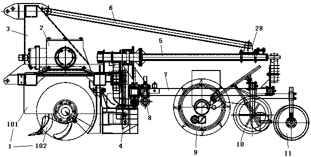
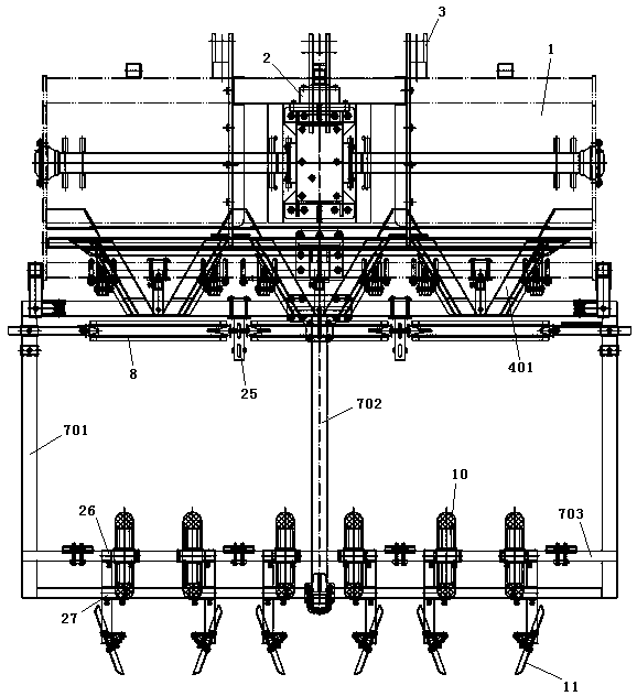
[0031] Embodiment 1: as Figure 1-7 As shown, a rotary tillage, ridge, and film-covering combined operation machine for sloping land includes a rotary tiller 1. The frame 101 of the rotary tiller 1 is fixedly connected with a gearbox assembly 2 by bolts and welded with a suspension frame. Assembly 3, the power output end of the gearbox assembly 2 drives the cutter shaft assembly 102 of the rotary tiller 1, the rear end of the rotary tiller 1 is equipped with a ridging device 4, and several groups of ridging plates are arranged on the ridging device 4 401; also includes a cantilever 5, a diagonal tie rod 6 and a film-coated frame 7; the cantilever 5 is arranged on the cantilever 5 on the rotary tiller 1, and the cantilever 5 extends to the rear of the rotary tiller 1, and the two ends of the diagonal tie rod 6 Respectively hinged on the suspension frame assembly 3 and the cantilever 5; the front and rear ends of the laminating frame 7 are rotatably connected to the cantilever 5...
Embodiment 2
[0042] Embodiment 2: This embodiment is a further improvement of Embodiment 1. The main improvement is that when Embodiment 1 is working, the laminating frame 7 is not restricted, and excessive rotation is prone to occur; while in this embodiment , can avoid the above defects, specifically:
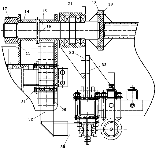
[0043] Also comprise the limit mechanism that is located at the two sides of rotary cultivator 1, stop rotating when the both sides of lamination frame 7 touches limit mechanism; Described limit mechanism includes adjusting sleeve 29 and limit rod 30, adjust The sleeve 29 is welded on both sides of the frame 101 of the rotary tiller 1, and the stop rod 30 can move up and down and is connected to the adjustment sleeve 29; the stop rod 30 is L-shaped, and several adjustment rods 30 are provided Hole 32, the adjustment sleeve 29 is equipped with not less than two screw rods 31, the limit rod 30 is plugged into the adjustment sleeve 29, and the screw rod 31 passes through the adjustment hole ...
PUM
 Abstract
Description
Claims
Application Information
 - R&D
- Intellectual Property
- Life Sciences
- Materials
- Tech Scout
- Unparalleled Data Quality
- Higher Quality Content
- 60% Fewer Hallucinations
Browse by: Latest US Patents, China's latest patents, Technical Efficacy Thesaurus, Application Domain, Technology Topic, Popular Technical Reports.
© 2025 PatSnap. All rights reserved.Legal|Privacy policy|Modern Slavery Act Transparency Statement|Sitemap|About US| Contact US: help@patsnap.com


