Tank body high-temperature-resistant spongy ceramic filter

A ceramic filter, ceramic filtration technology, applied in the direction of fixed filter element filter, filtration separation, chemical instruments and methods, etc., can solve problems such as irregularity, speed reduction, liquid purity influence, etc.

Inactive Publication Date: 2020-04-28
邓珍翔
View PDF0 Cites 0 Cited by
  • Summary
  • Abstract
  • Description
  • Claims
  • Application Information

AI Technical Summary

Problems solved by technology

[0004] 1. For sponge-like ceramic filters, the through-holes connected to the outside world are relatively irregular and dense. When the filtered residue is larger than the through-hole, the residue will stick to the inside and continue to flow in the subsequent high-temperature liquid , it will slow down and even push it more and more inward
[0005] 2. When the high-temperature casting liquid is transported in the ceramic filter, when the temperature of the inner layer and the outer layer are different, water droplets will be generated outside the ceramic filter and will drop together at the output end of the high-temperature liquid, resulting in a decrease in the purity of the liquid. influences

Method used


Image

  • Tank body high-temperature-resistant spongy ceramic filter
  • Tank body high-temperature-resistant spongy ceramic filter
  • Tank body high-temperature-resistant spongy ceramic filter

Examples


Embodiment 1

[0030] as attached figure 1 To attach Figure 5 Shown:

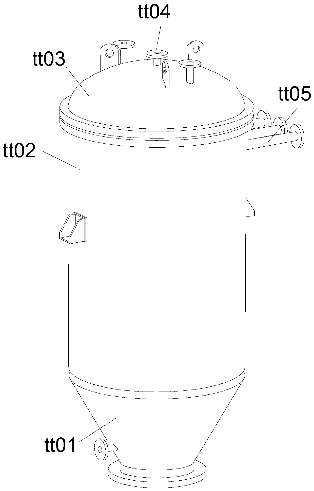
[0031] The invention provides a high-temperature-resistant sponge-shaped ceramic filter with a tank body, the structure of which includes a material delivery port tt01, a central control tank tt02, a top cover tt03, a ventilation port tt04, and a ceramic filter port tt05.

[0032] The upper surface of the material delivery port tt01 is connected to the lower surface of the central control tank tt02, the end of the central control tank tt02 away from the material delivery port tt01 is connected to the top cover tt03, and the vent tt04 runs through the top cover tt03 Inside, the ceramic filter port tt05 communicates with the central control tank tt02.

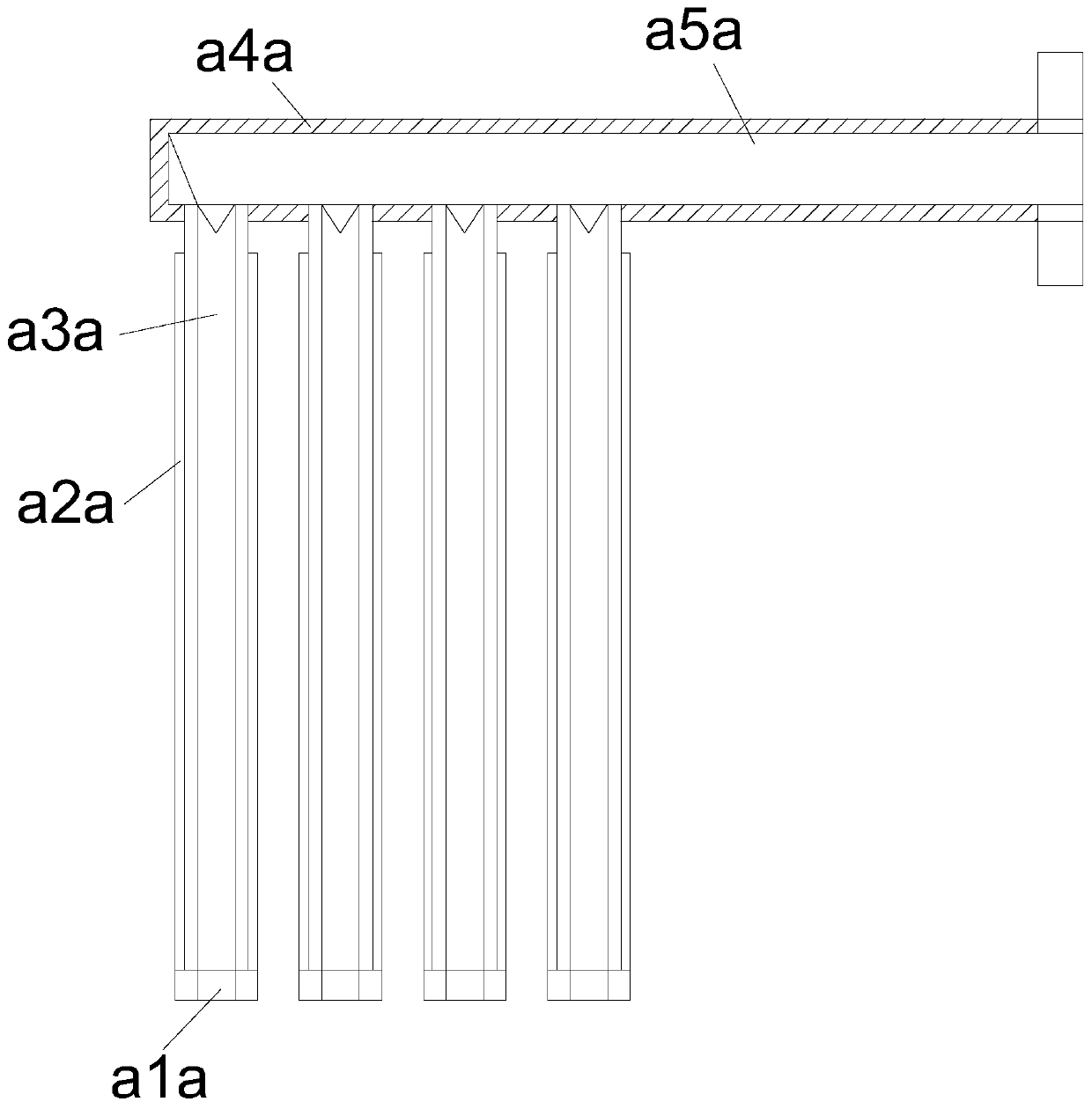
[0033] The ceramic filter port tt05 includes a filter port a1a, an outer suction ring a2a, a sponge ceramic body a3a, an outer pocket a4a, and a connecting pipe a5a. The filter port a1a is connected to the sponge ceramic body a3a, and the outer suction ring a2a fits On t...

Embodiment 2

[0040] as attached Figure 6 to attach Figure 7 Shown:

[0041] Wherein, the outer suction ring a2a includes an inclined vertex ss01, an outer soft edge ss02, an inner compartment ss03, and an inner channel ss04, the inclined vertex ss01 is connected with the outer soft edge ss02, and the inclined vertex ss01 is far away from the outer One end of the soft side ss02 is connected to the inner compartment ss03, the inner compartment ss03 is embedded with the inner channel ss04 and is located on the same axis, the inclined apex angle ss01 is evenly distributed in a circle, and the inner compartment ss03 It is a ring-shaped structure, the outer soft side ss02 plays a protective role for the internal parts, the inclined top angle ss01 assists the outer layer to fit the shape of the connected parts, and the inner partition ss03 separates the two sides.

[0042] Wherein, the inclined apex angle ss01 includes the inclined ball xx01, the abutment angle xx02, the extended welt xx03, t...


PUM


Abstract

The invention discloses a tank body high-temperature-resistant spongy ceramic filter which structurally comprises a material conveying port a central control tank and a top sealing cover, the upper surface of the conveying port is connected with the lower surface of the central control tank; liquid can be inputted into the inner sponge ceramic body through a connecting pipe; when liquid passes through the interior of the sponge ceramic body, impurities in the passing liquid can be adhered and retained by the surface of the sponge filter port. When high-temperature casting liquid is filtered and internal impurities are adhered to the interior of the spongy ceramic body, conveying distance can be extended in the continuous conveying process, smooth conveying is completed and subsequent treatment is performed later so that water mist is generated on the surface of the sponge ceramic body, the inclined vertex angle attached to the surface of the inner interlayer assists the outer layer inbeing attached to the appearance of the connected part, the ejector head can push the suction angle to be attached to the inner interlayer, and he water mist generated by the outer layer can be adsorbed in time and cannot slide down along with liquid to be mixed into a whole when the inner temperature and the outer temperature are different.

Description

technical field [0001] The invention belongs to the field of high-temperature structural ceramics, and more specifically relates to a high-temperature-resistant sponge ceramic filter for a tank body. Background technique [0002] For the liquid of the casting item, it needs to be melted at high temperature, and the purity is adjusted and extracted in the input ceramic filter, and the impurities inside will stick to the inside of the sponge-like ceramic filter, so that it can make the cast object more pure after the output is extracted. For smooth and hard effects. [0003] Based on the above-mentioned inventor's discovery, the existing high-temperature-resistant ceramic filter mainly has the following deficiencies, such as: [0004] 1. For sponge-like ceramic filters, the through-holes connected to the outside world are relatively irregular and dense. When the filtered residue is larger than the through-hole, the residue will stick to the inside and continue to flow in the ...

Claims


Application Information

Patent Timeline
Patent Type & Authority Applications(China)
IPC IPC(8): B01D29/35B01D29/52
CPCB01D29/35B01D29/52
Inventor 邓珍翔
Owner 邓珍翔
Why Eureka
Try Eureka