Supercharge Your Innovation With Domain-Expert AI Agents!

Waste gas treatment and purification equipment

A technology for purification equipment and waste gas treatment. It is applied in gas treatment, chemical instruments and methods, and dispersed particle filtration. It can solve problems such as troublesome installation and maintenance, save materials and improve treatment effects.

Inactive Publication Date: 2020-04-28
吴晓敏
View PDF7 Cites 1 Cited by
  • Summary
  • Abstract
  • Description
  • Claims
  • Application Information

AI Technical Summary

Problems solved by technology

[0003] The high position of the exhaust pipe causes workers to use ladders or other tools to climb to the outlet of the exhaust pipe when installing the exhaust gas treatment equipment; in addition, when the exhaust gas treatment equipment needs to replace the purification components, it is still necessary to manually climb with the aid of a cloud ladder In this way, the installation and later maintenance are very troublesome

Method used


Image

  • Waste gas treatment and purification equipment
  • Waste gas treatment and purification equipment
  • Waste gas treatment and purification equipment

Examples


Embodiment 1

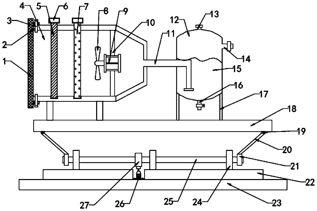
[0027] see figure 1 , in Embodiment 1 of the present invention, an exhaust gas treatment and purification equipment, which includes: a base 23, a backing plate 22 and a mounting seat 18, the backing plate 22 is arranged on the upper end of the base 23, and a lifting assembly is installed on the upper end of the backing plate 22. The upper end of the component is provided with a mounting seat 18, and the left and right sides of the lower end of the mounting seat 18 are provided with hinged blocks 19, and the mounting seat 18 is installed on the upper end of the lifting assembly through the hinged block 19;

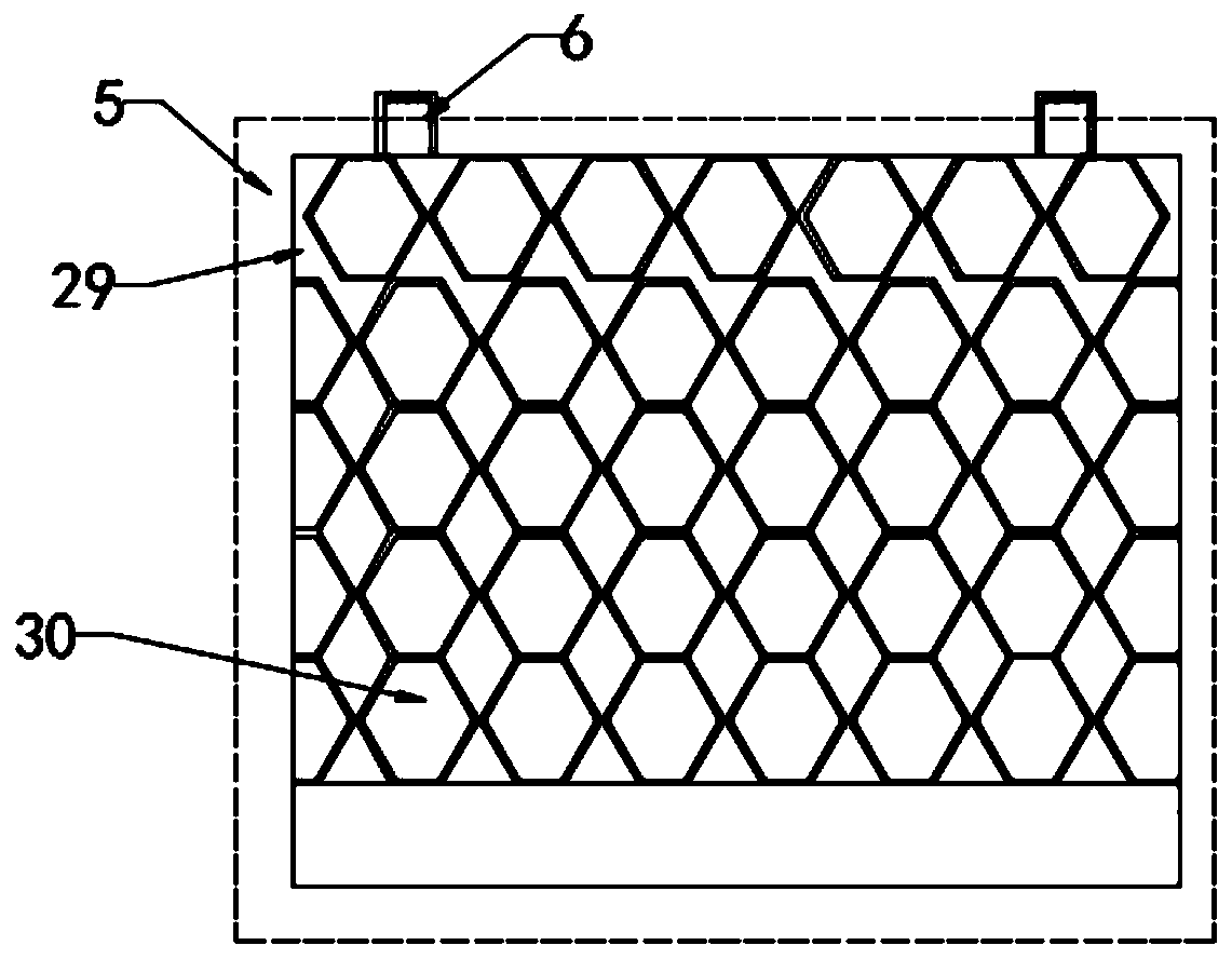
[0028] The left side of the upper end of the mounting seat 18 is provided with a purification box 2, and the purification box 2 is installed on the upper end of the mounting seat 18 through a support leg 17. The interior of the purification box 2 is a purification chamber 4, and the interior of the purification chamber 4 is provided with a purification assembly and an air su...

Embodiment 2

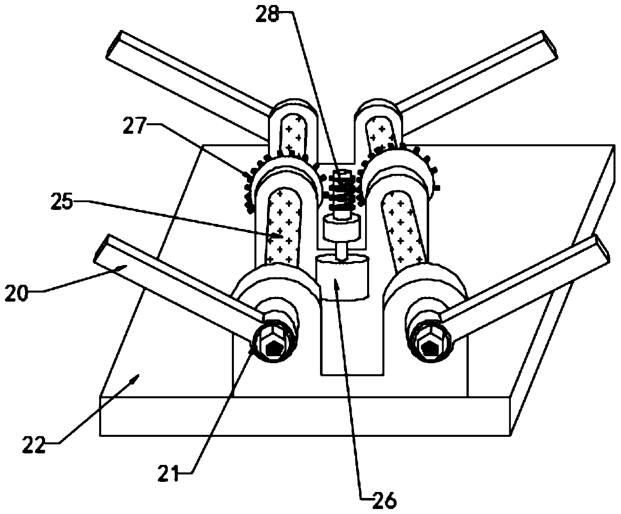
[0036] see figure 2 , further, the lifting assembly includes a rotating shaft 25, a worm 28 and a motor 26, the number of rotating shafts 25 is two, and one rotating shaft 25 passes through three limit blocks 24 at the same time, and the limit block 24 is installed on the upper end of the backing plate 22 , the rotating shaft 25 passes through the end portion of the limit block 24 on the left and right sides to be provided with a fixed ring 21, and a lifting frame 20 is installed and fixed on one side of the fixed ring 21, and the upper end of the lifting frame 20 is hingedly connected with the hinge block 19;

[0037] Specifically, a gear 27 is installed in the middle of the two rotating shafts 25, and a worm 28 is connected with a screw interference fit between the gears 27 on the two rotating shafts 25, and the lower end of the worm 28 is connected with the drive shaft of the motor 26, and the motor 26 is installed and fixed. on the backing plate 22;

[0038]Start the mot...


PUM


Abstract

The invention relates to the field of waste gas purification equipment, and particularly discloses waste gas treatment and purification equipment. The equipment comprises a base, a base plate and a mounting seat, the base plate is arranged at the upper end of the base, a lifting assembly is installed at the upper end of the base plate, the mounting seat is arranged at the upper end of the liftingassembly, and a purification box is arranged on the left side of the upper end of the mounting seat. A purification assembly and a suction assembly are arranged in the purification cavity. A neutralizing tank is arranged on the right side of the upper end of the mounting seat, and neutralizing liquid is injected into the neutralizing tank; the purification box communicates with the neutralizationtank through a breather pipe; according to the waste gas treatment and purification equipment, the height of the mounting seat can be adjusted through the lifting assembly, a user can conveniently conduct mounting according to the height of a waste gas opening, and the user can conveniently replace the purification assembly or fill neutralization liquid in time when the purification box or the neutralizing tank loses the effect.

Description

technical field [0001] The invention relates to the field of waste gas purification equipment, in particular to waste gas treatment and purification equipment. Background technique [0002] Exhaust gas refers to the poisonous and harmful gas emitted by human beings in the process of production and life, especially chemical plants, steel plants, pharmaceutical factories, coking plants and oil refineries, etc. The exhaust gas emitted has a strong smell, which seriously pollutes the environment and affects human health. Due to its light specific gravity, the exhaust gas will always be in a floating state; usually, in order to improve the exhaust gas discharge efficiency generated during production, the outlet height of the exhaust pipe is generally set at a high position. [0003] The high position of the exhaust pipe causes workers to use ladders or other tools to climb to the outlet of the exhaust pipe when installing the exhaust gas treatment equipment; in addition, when the...

Claims


Application Information

Patent Timeline
IPC IPC(8): B01D53/78B01D46/12B01D53/40B01D53/42
CPCB01D46/12B01D53/40B01D53/42B01D53/78B01D2258/02
Inventor 吴晓敏
Owner 吴晓敏
Features
  • R&D
  • Intellectual Property
  • Life Sciences
  • Materials
  • Tech Scout
  • Unparalleled Data Quality
  • Higher Quality Content
  • 60% Fewer Hallucinations
Learn More