Air pressure dynamic load testing system capable of achieving end face self-cleaning for driving axle assembly
A drive axle assembly and testing system technology, which is applied in cleaning methods and tools, cleaning methods using tools, liquid tightness measurement using liquid/vacuum degree, etc., can solve the problem of axle housing leakage and air tightness test results. Accuracy, drive axle oil leakage and other problems, to achieve the effect of improving accuracy
- Summary
- Abstract
- Description
- Claims
- Application Information
AI Technical Summary
Problems solved by technology
Method used
Image
Examples
Embodiment 1
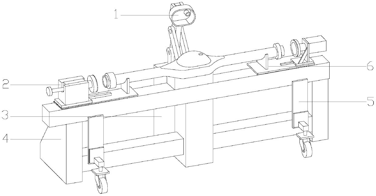
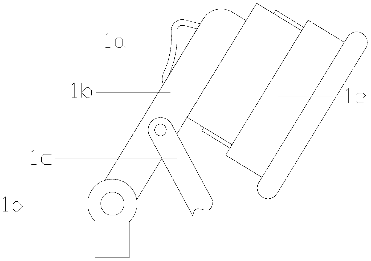
[0031] see Figure 1-Figure 6, the present invention provides a pneumatic dynamic load testing system for a self-cleaning drive axle assembly. The fixed frame 6, the equipment supporting frame 4 is horizontally installed on the ground, the moving wheel frame 5 and the equipment supporting frame 4 are fixed together by bolts, and the drive axle fixing frame 6 is horizontally installed on the left and right sides of the upper surface of the equipment supporting frame 4 At both ends, the drive axle sealer 2 is welded together with the drive axle fixing frame 6, the drive air pump 3 is located behind the equipment support frame 4, the inflator 1 and the drive air pump 3 are connected to each other, and the inflator 1 is composed of Inflatable sealing head 1a, sealing head connecting rod 1b, driving arm 1c, fixed shaft 1d, first cleaning device 1e, and second cleaning device 1f, the fixed shaft 1d is perpendicular to the driving air pump 3, and the sealing head The bottom of the c...
Embodiment 2
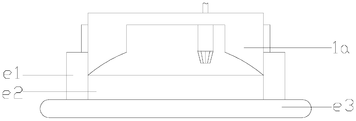
[0034] see Figure 7-Figure 11 , the second cleaning device 1f is composed of a fastening rod f1, a compression structure f2, and a rotary cleaner f3, the fastening rod f1 is tightly fastened with the inflatable sealing head 1a, and the compression structure f2 is located below the fastening rod f1, The rotary cleaners f3 are distributed in the compression structure f2, and the compression structure f2 and the rotary cleaners f3 are perpendicular to each other. The compression structure f2 is composed of an exhaust disc f21, a compression tube f22, a fixed suction cup f23, a rotating groove f24, and a driving guide rod f25. The top of the compression tube f22 is closely attached to the buckle rod f1, and the exhaust disc f21 The top of the compression tube f22, the driving guide rod f25 is located at the bottom of the exhaust pan f21, the fixed suction cup f23 is installed at the bottom of the compression tube f22, and the rotating groove f24 is nested between the fixed suctio...
PUM
 Abstract
Description
Claims
Application Information
 - R&D
- Intellectual Property
- Life Sciences
- Materials
- Tech Scout
- Unparalleled Data Quality
- Higher Quality Content
- 60% Fewer Hallucinations
Browse by: Latest US Patents, China's latest patents, Technical Efficacy Thesaurus, Application Domain, Technology Topic, Popular Technical Reports.
© 2025 PatSnap. All rights reserved.Legal|Privacy policy|Modern Slavery Act Transparency Statement|Sitemap|About US| Contact US: help@patsnap.com


