A hand-held label remover for shelves
A technology of remover and label, applied in cleaning methods and utensils, chemical instruments and methods, cleaning methods using liquids, etc., can solve the problems of affecting appearance, effort, trouble, etc., and achieve the effect of convenient handling
- Summary
- Abstract
- Description
- Claims
- Application Information
AI Technical Summary
Problems solved by technology
Method used
Image
Examples
Embodiment 1
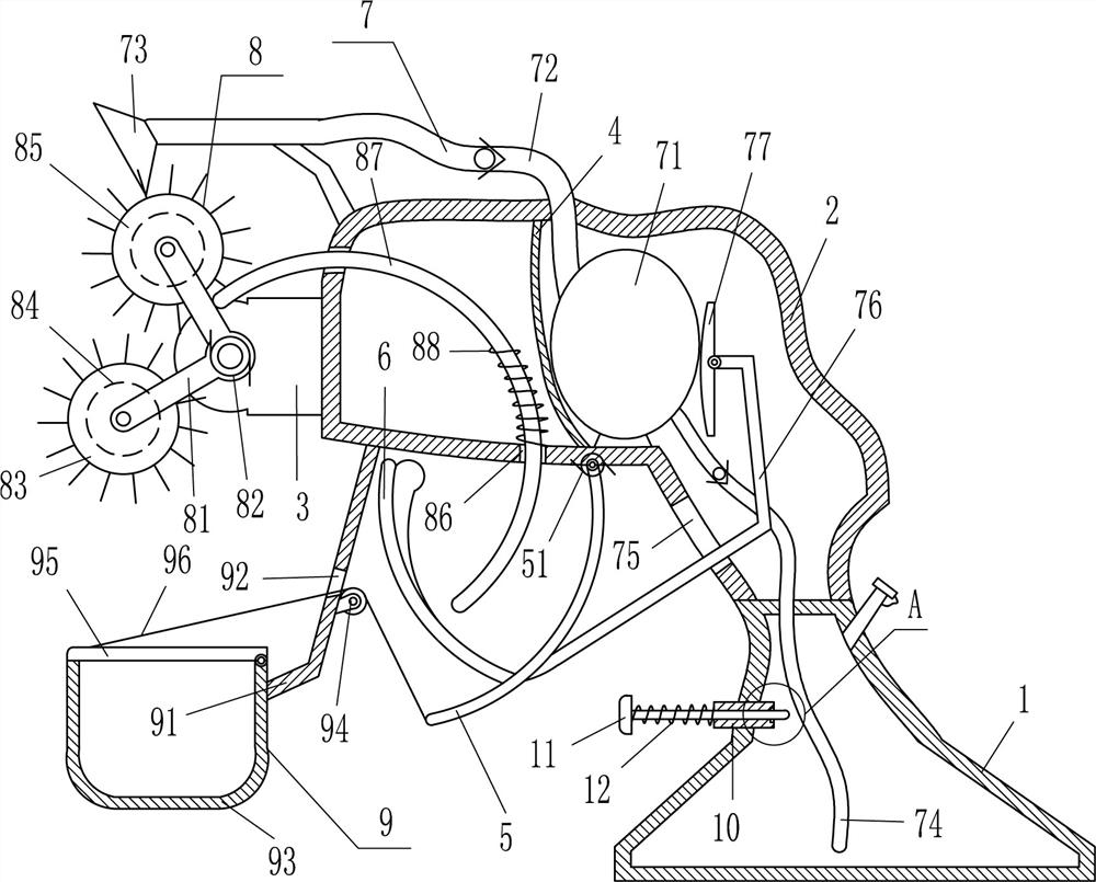
[0017] see figure 1 , this application provides a hand-held label remover for shelves, including a liquid tank 1, a housing 2, a fixed block 3, a fixed plate 4, a pull rod 5, a first torsion spring 51, an arc-shaped contact rod 6, a liquid spray Mechanism 7 and removal mechanism 8, the outer top of the liquid tank 1 is fixed with the casing 2, the middle of the left side of the outer casing 2 is fixed with a fixing block 3, and there is a label between the fixing block 3 and the left part of the casing 2. The cleaning mechanism 8 for cleaning has a fixed plate 4 fixedly connected between the left side and the inner bottom of the inner top of the casing 2. The right part of the casing 2 is provided with a liquid spraying mechanism 7 that can spray the solvent. The plate 4 cooperates with the liquid tank 1, a pull rod 5 is hinged on the right side of the outer bottom of the shell 2, a first torsion spring 51 is provided at the hinged place between the pull rod 5 and the shell 2,...
Embodiment 2
[0024] On the basis of Example 1, see figure 1 , and also includes a collection mechanism 9 that can collect paper scraps. The collection mechanism 9 includes a support plate 91, a collection frame 93, a wire wheel 94, a cover plate 95 and a pull wire 96. The left side of the outer bottom of the housing 2 is fixed with a support plate. 91. The rear end of the support plate 91 is fixed with a collection frame 93 that can collect paper scraps, a cover plate 95 is hinged on the top right side of the collection frame 93, the cover plate 95 cooperates with the collection frame 93, and a wire hole 92 is opened in the middle of the support plate 91 , the wire wheel 94 is installed on the lower part of the right side of the support plate 91 , the tail end of the pull rod 5 is connected with a pull wire 96 , and the tail end of the pull wire 96 bypasses the wire wheel 94 and then passes through the wire hole 92 to connect with the top left side of the cover plate 95 .
[0025] When the...
Embodiment 3
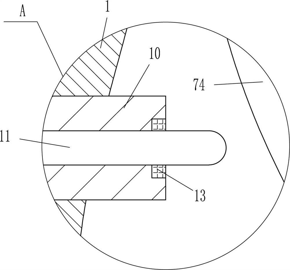
[0027] On the basis of Example 2, see figure 1 and figure 2 , and also includes a guide sleeve 10, a T-bar 11, a second spring 12 and a sealing ring 13. A guide sleeve 10 is embedded in the upper left side of the liquid tank 1, and a T-bar 11 is slidably installed in the guide sleeve 10. , a second spring 12 is wound between the left side of the T-bar 11 and the left side of the guide sleeve 10 , a sealing ring 13 is embedded in the right part of the inner wall of the guide sleeve 10 , and the sealing ring 13 is in contact with the T-bar 11 Cooperate.
[0028] When the operator pulls the pull rod 5 to swing to the right and contacts the T-bar 11, the pull rod 5 can be stopped, indicating that the solvent has been sprayed on the label, and the second brush cylinder 85 needs to be replaced to remove the label. Continue to pull the pull rod 5 to swing to the right, the pull rod 5 drives the T-bar 11 to move to the right, the second spring 12 is compressed, and the sealing ring...
PUM
 Abstract
Description
Claims
Application Information
 - R&D Engineer
- R&D Manager
- IP Professional
- Industry Leading Data Capabilities
- Powerful AI technology
- Patent DNA Extraction
Browse by: Latest US Patents, China's latest patents, Technical Efficacy Thesaurus, Application Domain, Technology Topic, Popular Technical Reports.
© 2024 PatSnap. All rights reserved.Legal|Privacy policy|Modern Slavery Act Transparency Statement|Sitemap|About US| Contact US: help@patsnap.com


