A method for removing the shaft core of the vacuum idler roller of a high-speed household paper machine

A vacuum and idler technology, which is applied in the direction of hand-held tools and manufacturing tools, can solve the problems of increasing the labor force of operators, shortening the service life of equipment, and unusable equipment due to damage, so as to shorten disassembly time, improve disassembly efficiency, and reduce The effect of wear rate

Active Publication Date: 2021-04-23
舒昕科技有限公司
View PDF13 Cites 0 Cited by
  • Summary
  • Abstract
  • Description
  • Claims
  • Application Information

AI Technical Summary

Problems solved by technology

[0002] At present, the technological innovation of equipment in the papermaking industry is advancing by leaps and bounds, the speed of equipment is getting faster and faster, and the width of base paper is getting wider and wider. Roller, suction box and other devices, according to the actual operation of the equipment, the dehydration capacity of the vacuum cage and the roller will become worse and worse with time, and the mesh cage and the core of the roller need to be pulled out for maintenance and cleaning, but at present There is no special extraction equipment for mesh cages and idler cores, all of which are manually disassembled, which is difficult to disassemble and increases the labor intensity of the operator. The top wire of the original equipment is seriously corroded and fails when it is reused, causing damage to the inner wire Cracking, so that the equipment is damaged and cannot be used, shortens the service life of the equipment, and causes great economic losses

Method used


Image

  • A method for removing the shaft core of the vacuum idler roller of a high-speed household paper machine
  • A method for removing the shaft core of the vacuum idler roller of a high-speed household paper machine
  • A method for removing the shaft core of the vacuum idler roller of a high-speed household paper machine

Examples


Embodiment 1

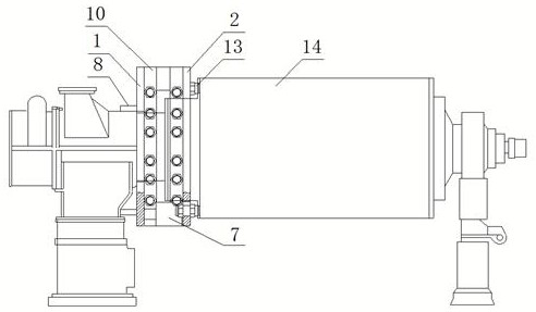
[0032] When using this device, the first support plate 1 and the second support plate 2 are respectively installed on the predetermined positions on the vacuum roller body through the connecting plate 10 and the fastening bolts, so that the baffle plate 8 and the vacuum roller body 14 The bracket is in contact with each other, the top wire 13 is in contact with the end cover, and a hydraulic jack 7 is evenly arranged between the first support plate 1 and the second support plate 2, and then the hydraulic jack is controlled to work so that the first support plate 1 and the second support plate The distance between the plates 2 increases, and then the top wire will make the shaft core out (the working process is similar to the process of separating the sword from the scabbard), and complete the disassembly of the shaft core; The core is disassembled, which shortens the disassembly time, improves the disassembly efficiency, reduces the number of operators involved, reduces the lab...


PUM


Abstract

The invention provides a method for removing a shaft core of a vacuum idler roller of a high-speed household paper machine, and mainly relates to the field of removing the shaft core of a vacuum idler roller. A method for removing a shaft core of a vacuum idler roller of a high-speed household paper machine, comprising a first support plate and a second support plate, the first support plate is composed of a first fixing plate and a second fixing plate, and the second support plate It consists of a third fixing plate and a fourth fixing plate, and a hydraulic jack is arranged between the first supporting plate and the second supporting plate. The beneficial effect of the present invention is that: the present invention disassembles the shaft core of the vacuum idler roller through the hydraulic jack, which shortens the disassembly time, improves the disassembly efficiency, reduces the number of operators involved, and reduces the labor intensity of the operators. , At the same time, it ensures that the end cap is evenly stressed, reduces the wear speed of the inner wire of the end cap, improves the service life of the equipment, and reduces the use cost.

Description

technical field [0001] The invention mainly relates to the technical field of removing a shaft core of a vacuum idler roller, in particular to a method for removing an axle core of a vacuum idler roller of a high-speed household paper machine. Background technique [0002] At present, the technological innovation of equipment in the papermaking industry is advancing by leaps and bounds, the speed of equipment is getting faster and faster, and the width of base paper is getting wider and wider. Roller, suction box and other devices, according to the actual operation of the equipment, the dehydration capacity of the vacuum cage and the roller will become worse and worse with time, and the mesh cage and the core of the roller need to be pulled out for maintenance and cleaning, but at present There is no special extraction equipment for mesh cages and roller cores, all of which are manually disassembled, which is difficult to disassemble and increases the labor intensity of the ...

Claims


Application Information

Patent Timeline
Patent Type & Authority Patents(China)
IPC IPC(8): B25B27/02
CPCB25B27/02B25B27/026
Inventor 孟昭金王艳军张德桥徐林孙式宫
Owner 舒昕科技有限公司
Why Eureka
Try Eureka