Insert sliding block structure of mold

A technology of inserts and sliders, which is applied to household components, household appliances, and other household appliances. It can solve problems such as scratches on the electroplating layer and affect the defective rate of injection molding products, so as to avoid scratches, reduce production costs, and improve quality. rate effect

Pending Publication Date: 2020-04-28
SHENZHEN KAIZHONG PRECISION TECH CO LTD
View PDF0 Cites 0 Cited by
  • Summary
  • Abstract
  • Description
  • Claims
  • Application Information

AI Technical Summary

Problems solved by technology

[0004] In view of this, the present invention proposes a mold insert slider structure to solve the problem that the electroplating layer on the hardware terminal is easily damaged by the mold when preparing a connector product with bent hardware terminals overmolded in the prior art. The inner wall of the insert hole is scratched, which affects the defective rate of injection molding products

Method used


Image

  • Insert sliding block structure of mold
  • Insert sliding block structure of mold
  • Insert sliding block structure of mold

Examples


Embodiment Construction

[0037] The technical solutions of the present invention will be clearly and completely described below in conjunction with the accompanying drawings. Apparently, the described embodiments are some of the embodiments of the present invention, but not all of them. Based on the embodiments of the present invention, all other embodiments obtained by persons of ordinary skill in the art without making creative efforts belong to the protection scope of the present invention.

[0038] In the description of the present invention, it should be noted that the terms "center", "upper", "lower", "left", "right", "vertical", "horizontal", "inner", "outer" etc. The indicated orientation or positional relationship is based on the orientation or positional relationship shown in the drawings, and is only for the convenience of describing the present invention and simplifying the description, rather than indicating or implying that the referred device or element must have a specific orientation, ...


PUM


Abstract

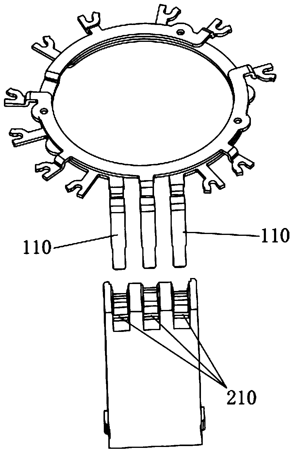
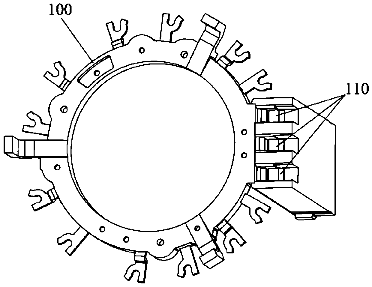
The invention discloses an insert sliding block structure of a mold. The insert sliding block structure comprises an insert, a sliding seat and a sliding block structure, wherein one side of the insert is provided with a terminal installation cavity provided with a side edge opening; the sliding block structure is slidably installed on the sliding seat and relatively gets close to or away from theside edge opening of the terminal installation cavity under action of driving force in the guide direction of the sliding seat; and the side wall, close to the insert, of the sliding block structureis provided with a pressing block which can stretch into the terminal installation cavity and cooperate with the insert to press a terminal located in the terminal installation cavity. The open type insert sliding block structure is adopted, scratching occurs when the terminal is installed into an insert hole can be avoided, in addition, the sliding block structure can adjust the terminal gap inwards or outwards within the acceptability limit according to injection molding easy deformation, the terminal deforming problem can be solved, the insert sliding block structure has the advantages thatthe percent of pass of manufactured connector products comprising bending terminals is high, and the production cost is low, and a mold mechanism meets the mass production requirement.

Description

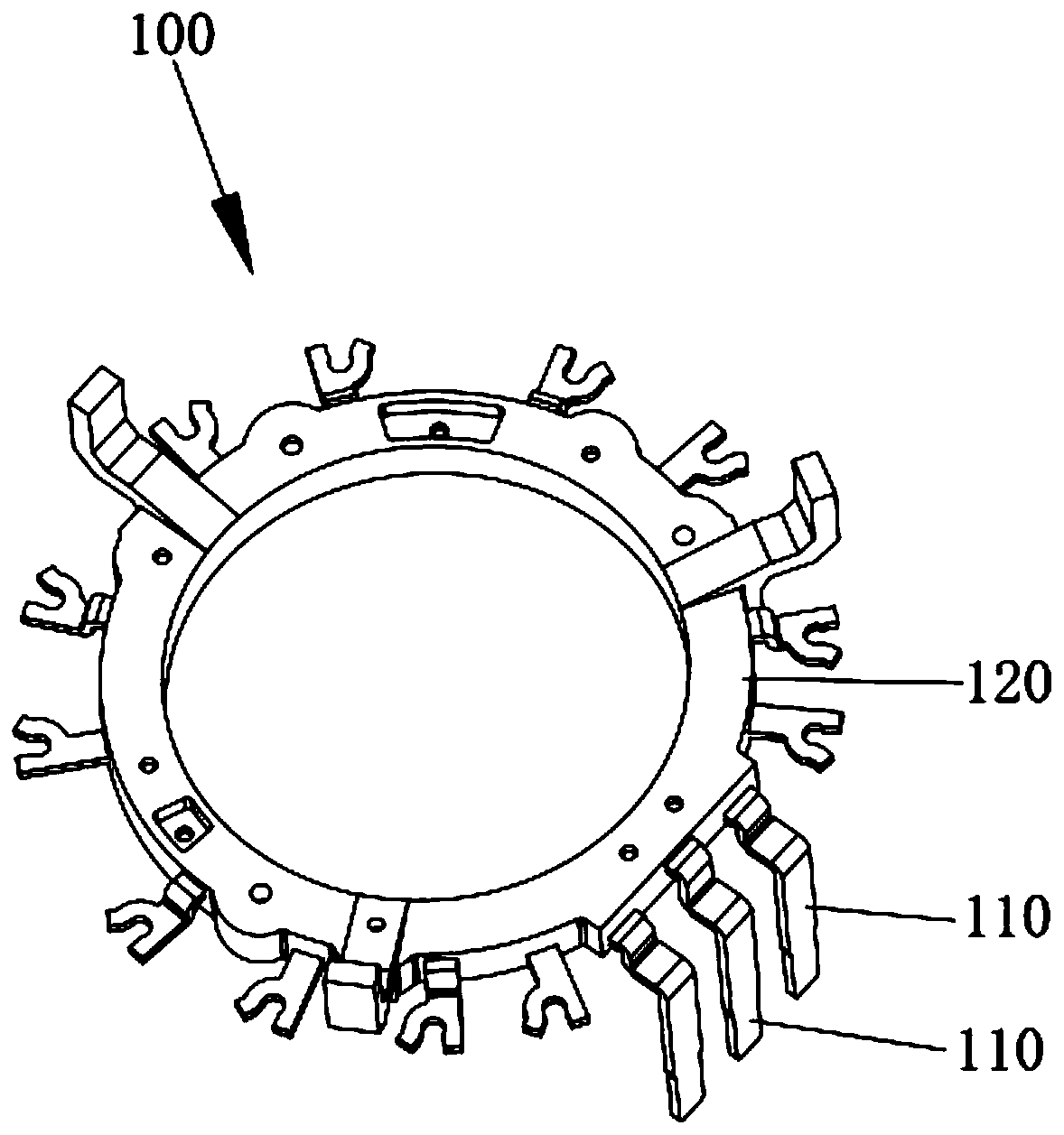
technical field [0001] The invention relates to the technical field of injection molds, in particular to an insert slider structure of a mold. Background technique [0002] in manufacturing figure 1 In the process of the connector 100 combined by the hardware terminal 110 and the plastic part 120, the hardware terminal 110 needs to be overmolded in the plastic part 120, and the overmolded hardware terminal 110 needs to be formed from the outer wall of the plastic part 120. exposed. According to different applications, the terminals of connector products need to be provided with different structures, and some connectors need to be provided with bent terminals. When manufacturing connectors with bent terminals, the bent terminals are generally manufactured first, then the bent terminals are inserted into the mold insert holes, and finally the plastic parts are injection molded to make a connector with hardware terminals overmolded product. [0003] In the prior art, manufa...

Claims


Application Information

Patent Timeline
Patent Type & Authority Applications(China)
IPC IPC(8): B29C45/33B29L31/36
CPCB29C45/33B29C45/332B29L2031/36
Inventor 周碧涛叶志强
Owner SHENZHEN KAIZHONG PRECISION TECH CO LTD
Why Eureka
Try Eureka