Concentric tool die
A tooling and mold technology, applied in the field of concentric tooling and molds, can solve the problems of affecting the effect of water treatment of electronic and electromagnetic equipment, failing to achieve the design purpose, affecting the effect of water treatment, etc., and achieves simple structure, convenient operation and convenient positioning. Effect
Pending Publication Date: 2020-04-28
张景尧
View PDF0 Cites 0 Cited by
- Summary
- Abstract
- Description
- Claims
- Application Information
AI Technical Summary
Problems solved by technology
If the emitter is slightly out of concentricity in the auxiliary machine, a magnetic bias phenomenon will occur in the auxiliary machine, which will directly affect the effect of electronic and electromagnetic equipment on water treatment, failing to achieve the design purpose
In order to ensure that the emitter seat is concentric with the inner wall of the auxiliary machine when installing the emitter seat, a concentric tooling mold was invented to solve the problem of affecting the water treatment effect due to the different tooling.
Method used
View moreImage
Smart ImageViewing Examples

Examples
Embodiment Construction
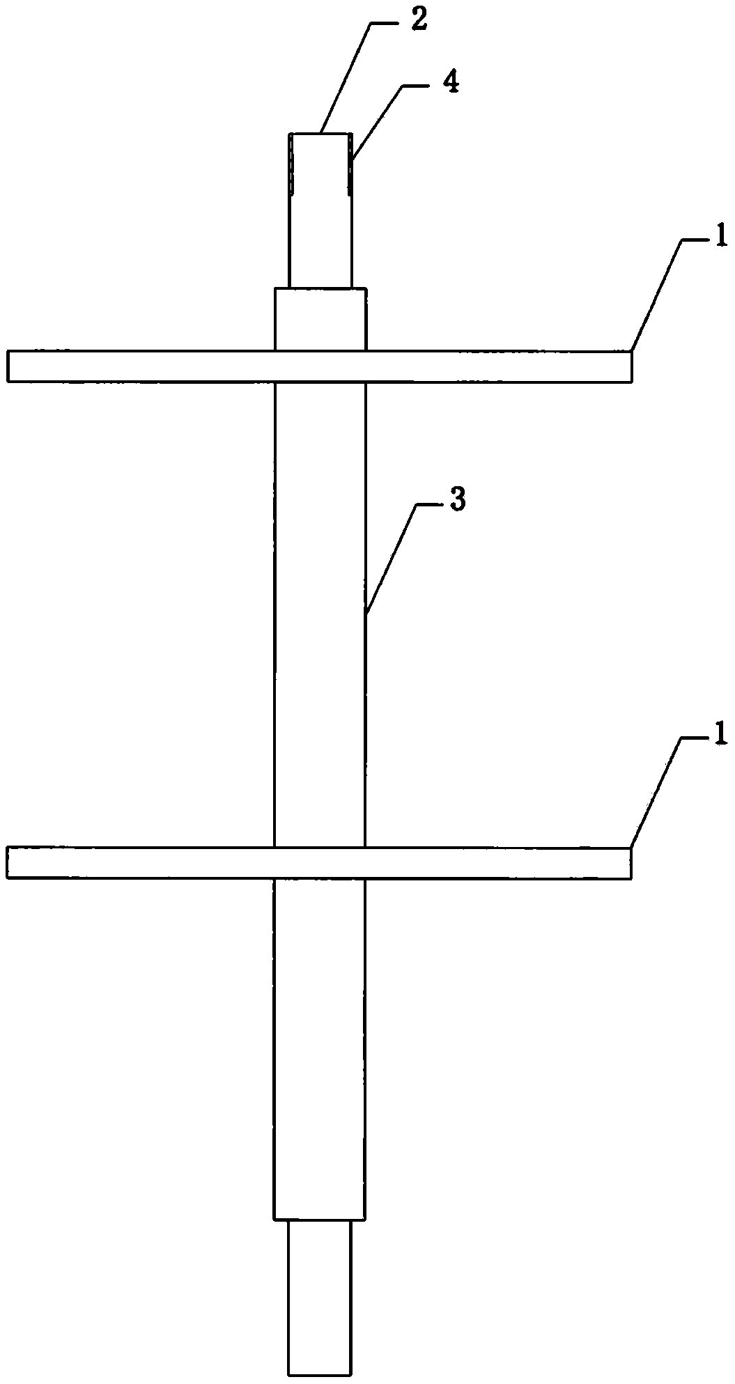
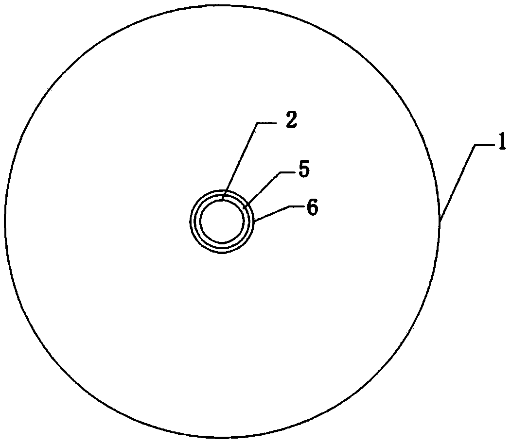
[0015] Such as Image 6 Shown: 7 is the auxiliary machine of water treatment equipment, when tooling 8 emitter seat, will Figure 5 insert Image 6 Inside the auxiliary machine of 7, and make 8 stuck in 5 and 6, the concentric positioning rod 2 passes through the concentric positioning tube 3 and make 4 on 2 and 9 on 8 dock, after the alignment is accurate, 8 and 7 are welded and fixed, In this way, the concentric precision of 8 and 7 is guaranteed.
Login to view more PUM
 Abstract
The invention discloses a concentric tool die which can be widely applied to electronic and electromagnetic water treatment equipment in manufacturing of an auxiliary machine and can ensure that an emitter is located in the middle of the auxiliary machine and the emitter is concentric with the inner wall of the auxiliary machine.
Description
[0001] Technology fields: [0002] The invention discloses a concentric tooling mold, which can be widely used in the manufacture of electronic and electromagnetic water treatment equipment to ensure that the emitter is in the middle of the auxiliary machine and ensure that the emitter is concentric with the inner wall of the auxiliary machine. Background technique: [0003] In the manufacture of electronic and electromagnetic water treatment equipment, due to the special properties of electronic and electromagnetic. If the emitter is slightly out of concentricity in the auxiliary machine, a magnetic bias phenomenon will occur in the auxiliary machine, which will directly affect the effect of electronic and electromagnetic equipment on water treatment, failing to achieve the design purpose. In order to ensure that the installation of the emitter seat is concentric with the inner wall of the auxiliary machine, a concentric tooling mold was invented, which solved the problem of ...
Claims
Login to view more Application Information
Patent Timeline
 IPC IPC(8): C02F1/00C02F1/48
CPCC02F1/00C02F1/48C02F1/484
Inventor 张景尧
Owner 张景尧
- R&D Engineer
- R&D Manager
- IP Professional
Why Eureka
- Industry Leading Data Capabilities
- Powerful AI technology
- Patent DNA Extraction
Try Eureka
Browse by: Latest US Patents, China's latest patents, Technical Efficacy Thesaurus, Application Domain, Technology Topic.
© 2024 PatSnap. All rights reserved.Legal|Privacy policy|Modern Slavery Act Transparency Statement|Sitemap