Robot for construction site construction management

A technology for construction management and construction sites, applied in construction, chemical instruments and methods, and the use of liquid separating agents, etc., can solve problems such as hazards and large dust, and achieve the effects of reducing physical damage and suppressing the content of dust

Active Publication Date: 2020-04-28
合肥速纳工程设计有限公司
View PDF11 Cites 0 Cited by
  • Summary
  • Abstract
  • Description
  • Claims
  • Application Information

AI Technical Summary

Problems solved by technology

[0003] Existing construction sites often have relatively large dust during construction, so construction workers are bound to have certain hazards in such an environment, so at present, sprinklers are used for dust removal, but the existing sprinklers They are all fixedly installed, so there is often some inconvenience when using them, so we propose a robot for construction management on construction sites to solve the above-mentioned problems

Method used


Image

  • Robot for construction site construction management
  • Robot for construction site construction management
  • Robot for construction site construction management

Examples


Embodiment 1

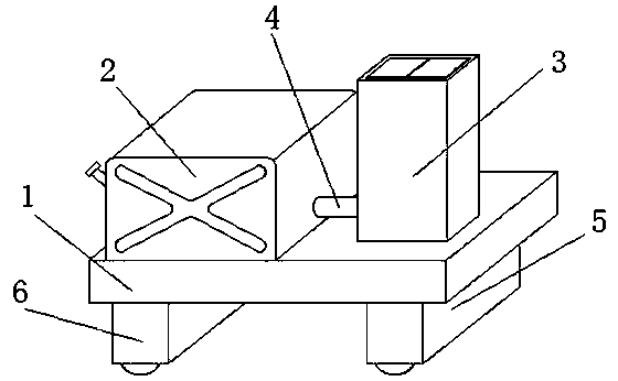
[0030] refer to Figure 1-6 In this embodiment, a robot for construction management on a construction site is proposed, which includes a base 1, a mounting cover 5 and a driving cover 6 are respectively fixedly installed on the bottom of the base 1, and two first wheels 33 are connected symmetrically in the mounting cover 5 , and the bottom ends of the two first wheels 33 all extend to the bottom of the installation cover 5, and the drive cover 6 is connected with two second wheels 45 for symmetrical rotation, and the bottom ends of the two second wheels 45 all extend to the drive cover 6, a water tank 2 and an installation box 3 are fixedly installed on the top of the base 1 respectively, and the installation box 3 is located on one side of the water tank 2, and a water pump 7 is fixedly installed on the inner wall of the bottom of the installation box 3, and the suction end of the water pump 7 is fixedly installed There is a connecting pipe 4, one end of the connecting pipe ...

Embodiment 2

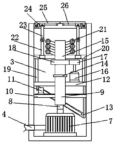
[0033] In this embodiment, a lifting plate 12 is fixedly installed on the moving tube 9, and the lifting plate 12 is slidably connected with the inner wall of the installation box 3. The bottom of the lifting plate 12 is fixedly installed with a connecting ring 13 that is arranged obliquely, and the connecting ring 13 is mounted on the box. The inwall of 3 is slidably connected with drive motor 11 positioned at lift plate 12 below, and the output shaft of drive motor 11 is connected with link ring 13 transmission, utilizes the inclined installation of link ring 13, can facilitate lift plate 12 longitudinal movement.

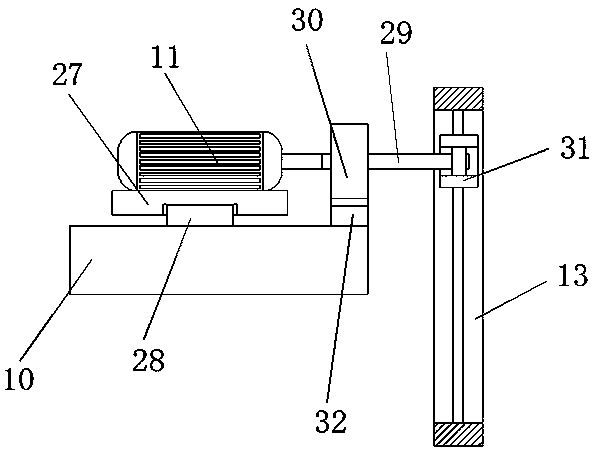
[0034] In this embodiment, the installation beam 10 located below the lifting plate 12 is fixedly installed on the inner wall of the installation box 3, and the drive motor 11 is slidably installed on the top of the installation beam 10, and a rotating shaft 29 is fixedly installed on the output shaft of the drive motor 11. The inner wall of connecting ring 13 is ...


PUM


Abstract

The invention belongs to the field of robots, and especially relates to a robot for construction site construction management. The robot is provided to solve the problem of certain use inconvenience of existing spraying devices which are all fixedly installed. The robot comprises a base, a mounting cover and a driving cover are fixedly mounted at the bottom of the base, two first wheels are symmetrically and rotationally connected into the mounting cover, the bottom ends of the two first wheels extend to the lower part of the mounting cover, and two second wheels are symmetrically and rotationally connected into the driving cover. A plurality of nozzles are moved to a position above the mounting box, and then a water pump and a rotating motor are started, so the purpose of spraying water can be achieved; and free movement of the robot can be achieved through the two first wheels and the two second wheels, so spraying can be conducted on all areas of the construction site, the content of dust can be effectively restrained, and harm to the body of a constructor is greatly reduced.

Description

technical field [0001] The invention relates to the technical field of construction robots, in particular to a construction management robot for a construction site. Background technique [0002] A construction site is a place where construction projects are being developed and civil engineering is being carried out. Its scope is often closed by hoardings, barbed wire or walls to restrict the entry and exit of personnel, materials, machinery and vehicles. There are property management administrators guarding. You may need to register your identity and wear a helmet when entering and exiting. [0003] Existing construction sites often have relatively large dust during construction, so construction workers are bound to have certain hazards in such an environment, so at present, sprinklers are used for dust removal, but the existing sprinklers They are all fixedly installed, so there is often some inconvenience when using them. Therefore, we propose a robot for construction m...

Claims


Application Information

Patent Timeline
Patent Type & Authority Applications(China)
IPC IPC(8): E01H3/02B01D47/06
CPCB01D47/06E01H3/02
Inventor 陈娜
Owner 合肥速纳工程设计有限公司
Why Eureka
Try Eureka