A method of making a selective emitter battery

A manufacturing method and emitter technology, applied in the field of solar cells, can solve problems such as unfavorable automation promotion, increased costs, and cumbersome process steps, and achieve an effect that is conducive to industrialized automated production

Active Publication Date: 2016-01-13
YINGLI ENERGY CHINA
View PDF6 Cites 0 Cited by
  • Summary
  • Abstract
  • Description
  • Claims
  • Application Information

AI Technical Summary

Problems solved by technology

In this way, after laser doping, the phosphorus source on the surface needs to be treated twice, the process steps are cumbersome, and the cost is high; on the other hand, in the prior art, high-temperature diffusion is performed before spraying the phosphorus source and laser doping to form a p-n junction. , the loading and unloading principles of the two devices are different, so it is not easy to connect the two devices, which is not conducive to the promotion of industrial automation

Method used


Image

  • A method of making a selective emitter battery
  • A method of making a selective emitter battery

Examples


Embodiment Construction

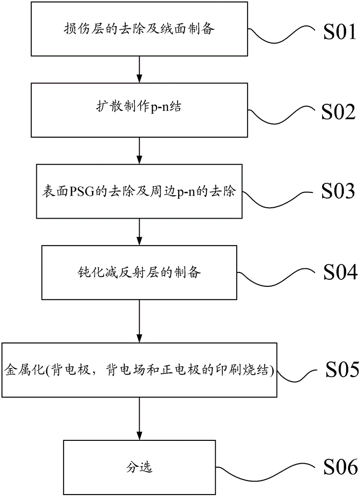
[0033] The invention discloses a method for manufacturing a selective emitter battery, which does not require special post-processing and does not need to add additional equipment, and is more conducive to industrialized automatic production.

[0034] The following will clearly and completely describe the technical solutions in the embodiments of the present invention with reference to the accompanying drawings in the embodiments of the present invention. Obviously, the described embodiments are only some, not all, embodiments of the present invention. Based on the embodiments of the present invention, all other embodiments obtained by persons of ordinary skill in the art without making creative efforts belong to the protection scope of the present invention.

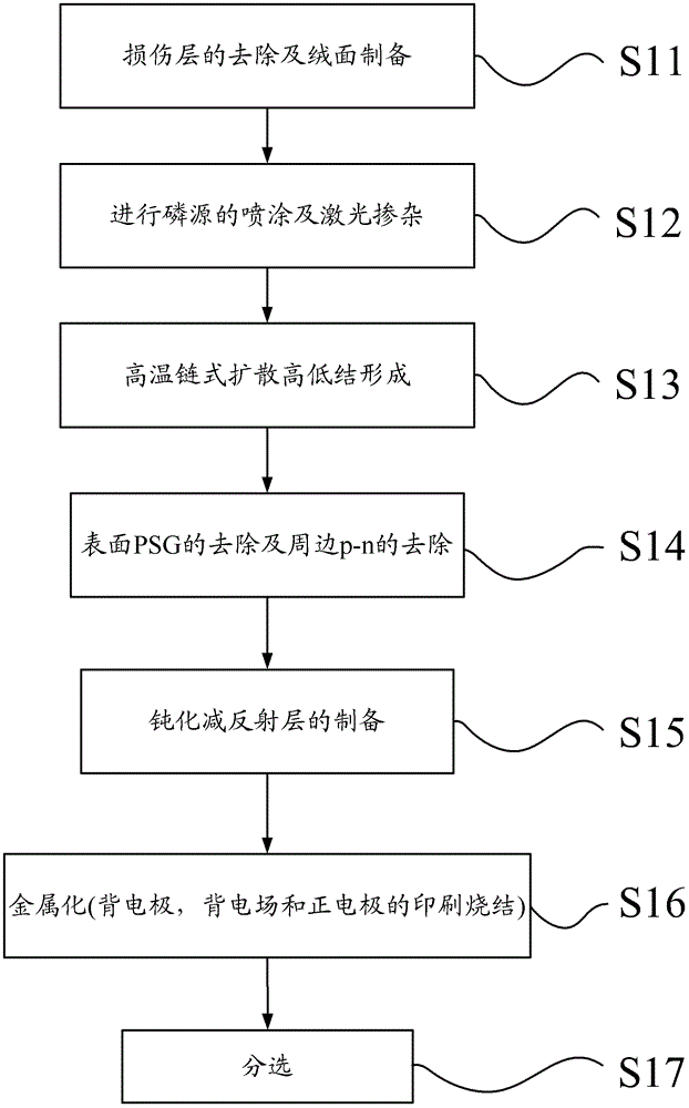
[0035] see figure 2 , the manufacturing method of the selective emitter battery provided by the embodiment of the present invention, comprising:

[0036] Step S11: Removal of the damaged layer and preparation of suede...


PUM


Abstract

The invention discloses a manufacturing method of a selective emitter cell, and the method comprises the steps: 1) removing the damage layer of a silicon chip and manufacturing a pile face on the surface of the silicon chip; 2) spraying phosphorus source and doping by utilizing laser on the silicon chip after the first step; 3) carrying out high-temperature chain-type diffusion for the sprayed and doped silicon chip to obtain p-n junctions of a zone outside the right positive electrode zone; 4) removing PSG on the surface of and p-n junctions around the silicon chip after the high-temperature chain-type diffusion; 5) depositing a layer of silicon nitride film which plays effects of reflection reduction and passivation on the surface of the silicon chip after the fifth step; 6) printing and sintering a back electrode, a back electric field, and a right electrode on the silicon chip with the silicon nitride film to metallize the electrodes and obtain the selective emitter cell; 7) testing each parameter of the selective emitter cell and grading the selective emitter cell according to the technology standard. The method can effectively improve the conversion efficiency of a solar cell and be used in production conveniently.

Description

technical field [0001] The invention relates to the technical field of solar cells, in particular to a method for manufacturing a selective emitter cell. Background technique [0002] As a clean and environmentally friendly new energy source, the application of solar cells is becoming more and more popular. But the cost of this battery is relatively high, which limits its rapid popularization. In order to reduce costs, it is necessary to continuously adopt new technologies to improve the conversion efficiency of solar cells. Among them, the selective emitter cell is a new process with simple process and can effectively improve the efficiency of solar cells. Based on the principle of selective emitter cells, there are various ways to realize this structure. However, many of these methods have cumbersome process steps and high cost, and are not suitable for industrial production. [0003] The production process of conventional solar cells is as follows: figure 1 mentioned...

Claims


Application Information

Patent Timeline
Patent Type & Authority Patents(China)
IPC IPC(8): H01L21/228H01L31/18
CPCY02P70/50
Inventor 史金超宋伟鹏杨伟光张东升解占壹马红娜
Owner YINGLI ENERGY CHINA
Why Eureka
Try Eureka