
Concrete pouring pipe device for preventing concrete segregation and method

A technology of concrete and pouring pipes, applied in dams, buildings, wall dams, etc., can solve the problems of difficult construction of cut-off walls, high cost of demolition, and overhead phenomena, and achieve the effect of avoiding concrete segregation

Active Publication Date: 2020-04-28
SINOHYDRO FOUND ENG
View PDF5 Cites 0 Cited by
  • Summary
  • Abstract
  • Description
  • Claims
  • Application Information

AI Technical Summary

Problems solved by technology

[0003] For the damming body, previous engineering experience mainly focused on dismantling and diverting water flow. However, for a damming body with a huge volume formed by a super-large collapse, the cost of demolition is very high, and it is difficult to find it near the project site. There are so many accumulations in a suitable site, so if we can make full use of the dams and directly use the dams to form the dam, it will eliminate harm and bring benefits, and turn waste into treasure.
However, for the geology of the dam body where the maximum depth of the cut-off wall exceeds 130m, the thickness of the wall exceeds 1.0m, and the boulder content exceeds 50%, the maximum particle size of the boulder exceeds 15 meters, the overhead phenomenon is serious, and the stratum has not been deposited and cemented. In terms of conditions, these unfavorable conditions have caused great difficulties in the construction of cut-off walls and posed great challenges to existing construction technologies. How to make the geological conditions of the above-mentioned dam body suitable for the construction of cut-off walls? There is no construction precedent at home and abroad

Method used


Image

  • Concrete pouring pipe device for preventing concrete segregation and method
  • Concrete pouring pipe device for preventing concrete segregation and method
  • Concrete pouring pipe device for preventing concrete segregation and method

Examples


Embodiment Construction

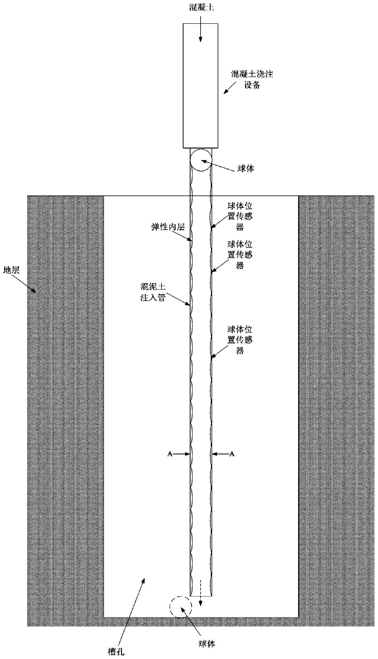
[0044] figure 1 The first embodiment of the concrete pouring pipe device for preventing concrete segregation of the present invention is shown. The concrete pouring pipe device for preventing concrete segregation in the first embodiment includes: concrete pouring equipment; a concrete pouring pipe docked with the concrete pouring equipment.

[0045] The concrete pouring pipe comprises: a plurality of pipe body sections; an elastic inner layer arranged in each pipe body section; a ball in frictional contact with the elastic inner layer; a plurality of ball position sensors arranged in the concrete pouring pipe.

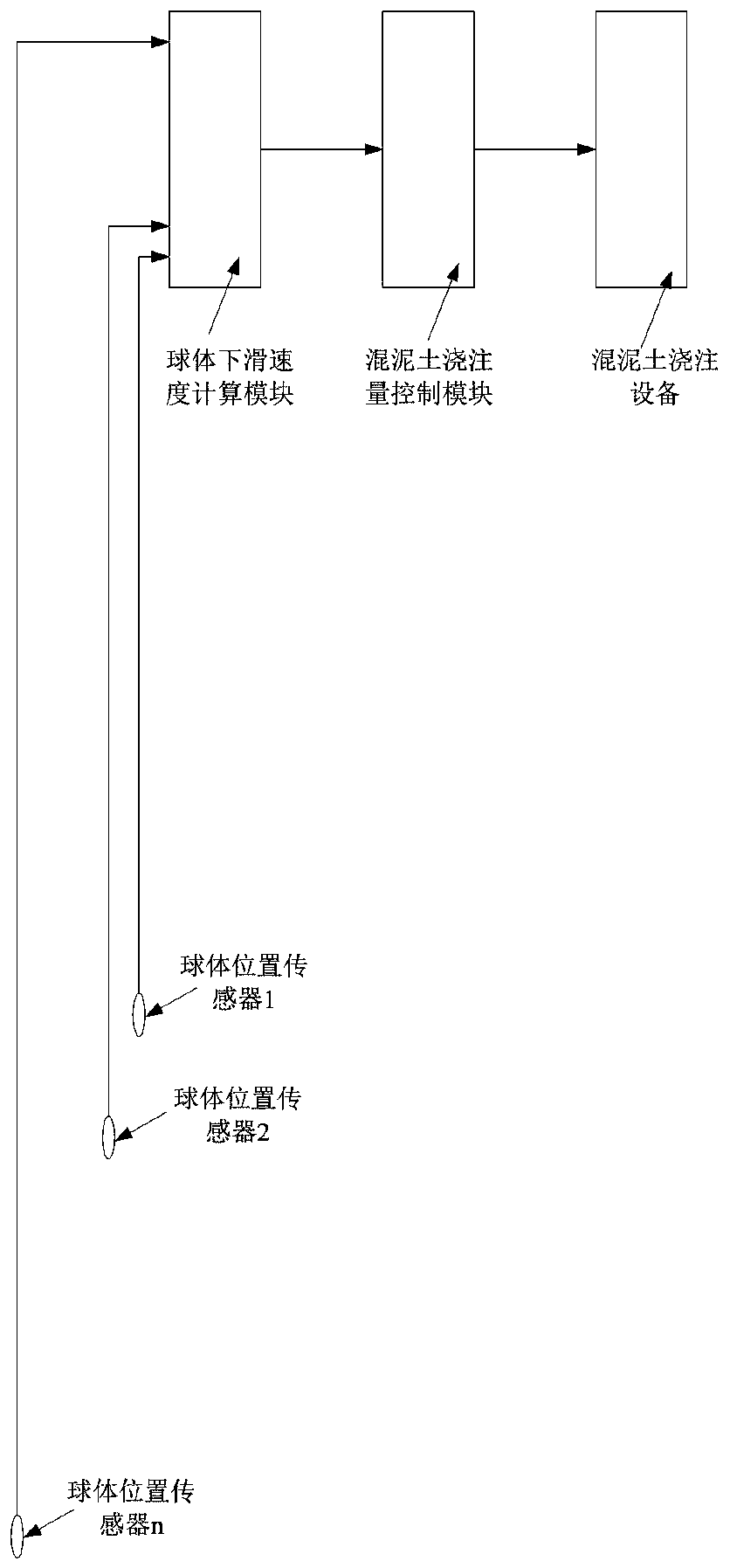
[0046] see figure 2 , the concrete pouring pipe device of the present invention also includes: a controller connected to the plurality of sphere position sensors, and the controller controls the concrete pouring of the concrete pouring equipment according to the preset corresponding relationship between the sphere sliding speed and the concrete pouring amount. Pourin...


PUM


Abstract

The invention discloses a concrete pouring pipe device for preventing concrete segregation and a method. The concrete pouring pipe device for preventing the concrete segregation and the method are used for grooving construction of a diaphragm wall of a landslide dam. The method comprise the steps that pre-explosion treatment is carried out on the axis of the diaphragm wall of the landslide dam, and boulders with large volume are broken into small stones; after the pre-explosion treatment is completed, pre-grouting treatment is carried out on the upstream and the downstream of the axis of the diaphragm wall of the landslide dam, and leakage channels on the upstream and the downstream of the axis of the diaphragm wall of the landslide dam are blocked; after the pre-grouting treatment is completed, the grooving construction of the diaphragm wall of the landslide dam is carried out, specifically, a groove hole is formed through drilling and hole cleaning construction with the axis of the diaphragm wall of the landslide dam as the benchmark, then a concrete pouring pipe is lowered, and concrete pouring equipment is in butt joint with the concrete pouring pipe; and the concrete pouring amount of the concrete pouring equipment is controlled according to the sliding speed of a ball body in the concrete pouring pipe, so that concrete slowly falls to the bottom of the groove hole along with the ball body until the diaphragm wall of the landslide dam is formed through pouring.

Description

technical field [0001] The invention relates to the field of water conservancy and hydropower engineering, in particular to a concrete pouring pipe device and a construction method for preventing concrete segregation. Background technique [0002] The barrier body was formed by earthquake collapse and landslides. Since the improvement of the barrier lake is imminent, the improvement of the barrier body needs to adhere to the working idea of ​​research, design, and treatment at the same time. It is necessary to carry out the implementation of risk reduction and flood control projects such as barrier body improvement as soon as possible. The damming body improvement is to carry out anti-seepage treatment and partial slope surface improvement on the damming body, weir foundation and bank slopes on both sides. The anti-seepage treatment of the damming body adopts the combination of anti-seepage wall and curtain grouting. [0003] For the damming body, previous engineering experi...

Claims


Application Information

Patent Timeline
IPC IPC(8): E02D15/02E02B7/08
CPCE02B7/08E02D15/02
Inventor 宗敦峰肖恩尚陈红刚孙亮宋伟孙仲彬赵明华张裕文
Owner SINOHYDRO FOUND ENG
Learn More